
Remember me


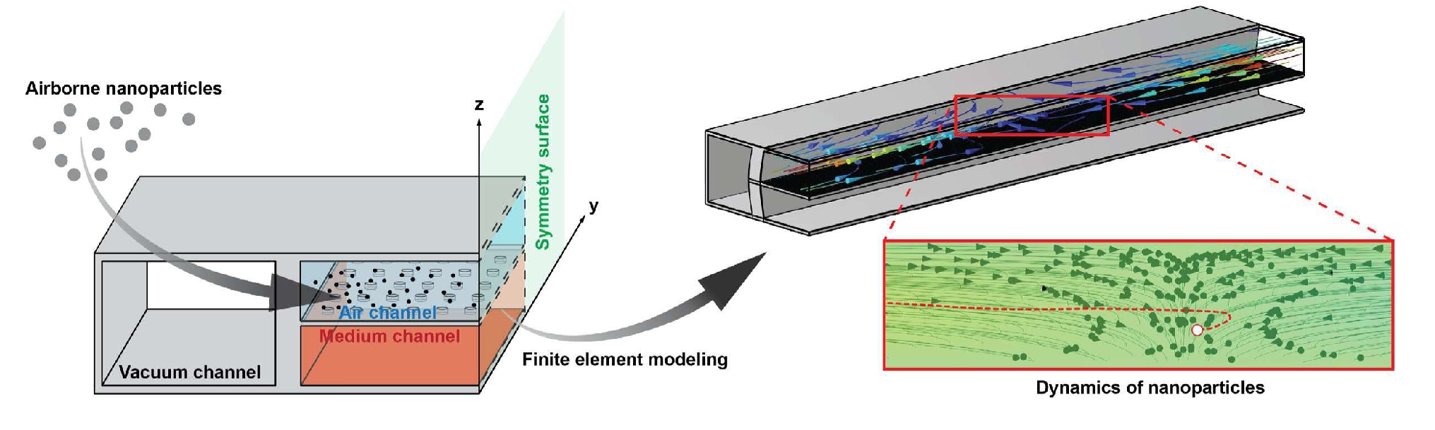
This section presents the numerical results from a 3D multi-physics simulation, evaluating the effects of key parameters—fluid flow rate, membrane porosity, and the intensity and frequency of membrane stretching—on the dynamics of NPs across different size ranges in a lung-on-a-chip. To better demonstrate the importance of such a comprehensive 3D model of a stretching lung-on-a-chip in accurately evaluating particle dynamics, the results are sequentially presented, covering: dynamics of nanoparticles in a fixed stretched lung-on-a-chip; fluid dynamics inside a sinusoidal stretched lung-on-a-chip; and Dynamics of nanoparticles in a sinusoidal stretched lung-on-a-chip. To highlight the need for such a 3D modeling, a comparative study was conducted at the outset between the current 3D simulation with an earlier 2D model [21] to assess the strengths and limitations of the 2D approach. The results are presented in Supplementary Section 2.
Dynamics of nanoparticles in a fixed stretched lung-on-a-chipBefore examining the dynamic effects of stretching, it is insightful to first assess the impact of stretching intensity on NP deposition and transfer rates under stationary conditions. To this end, two distinct membrane porosities of 3.6% and 30.5% are analyzed [11, 21]. These porosity values were selected based on prior experimental studies and represent two physiologically relevant regimes: a low-porosity membrane (3.6%) mimicking tighter epithelial barriers, and a high-porosity membrane (30.5%) designed for enhanced exchange between air and media channels. We also evaluate two different inflow rates: 0.72 μL/min and 2.4 μL/min. The influence of stretching intensity is illustrated with results for three scenarios, as shown in Fig. 5: No Stretching, 10% Membrane Strain, and 20% Membrane Strain. Stretching the membrane not only expands the cross-sectional area of the microchannel but also alters the porosity ratio of the membrane, as detailed in Table 2. The results clearly show that stretching the membrane increases its porosity, with particularly significant changes at lower porosity levels.
Fig. 5
a) Deposition and b) transfer rates of NPs with various diameters under different stretching of 30.5% porous membrane and two different inflow rates. c) Deposition and d) transfer rates of NPs with various diameters under different stretching of 3.6% porous membrane and two different inflow rates
Table 2 Effect of stretching on membrane size, porosity area, and porosity ratioWhen considering consistent inflow rates, the expansion of the microchannel inlet cross-section leads to reduced inflow velocities, which in turn increases the sedimentation rate. It is important to note that the sedimentation rate is directly proportional to the level of stretching but remains independent of the membrane porosity. This relationship is clearly demonstrated by identical outcomes in the summation of transfer and deposition rates for different porosities, as shown in Fig. 5.
The increased sedimentation rate, coupled with a higher porosity level caused by stretching, subsequently enhances the transfer rate, as depicted in Fig. 5b and d. The authors have observed that the transfer rate under stretching (\(_}\)) can be approximated by:
where \(_}\) is unstretched transfer rate. \(_\) signifies the ratio of sedimentation rates between the stretched and unstretched scenarios, obtained straightforwardly by summing the transfer and deposition rates. \(_\) shows the porosity ratio, calculated by dividing the stretched porosity by the unstretched porosity from Table 2. The validity of Eq. 11 can be exemplified, for instance with 500 nm particles at the inflow rate of 0.72 μL/min under 10% strain of the high-porosity membrane, where \(_}=0.2095\), \(_}=0.18\), \(_\cong 1.09\), \(_\cong 1.09\). In addition, the deposition rate also demonstrates an increase with the stretching of the membrane, as depicted in Fig. 5a and c. However, it’s noteworthy that for NPs with a high sedimentation rate, stretching the membrane primarily results in an augmented transfer rate with a minimal impact on the sedimentation rate that eventually leads to consistent or decreased deposition rates.
Fluid dynamics inside a sinusoidal stretched lung-on-a-chipBefore delving into the behavior of NPs, it is crucial to first understand the fluid dynamics within the microdevice under variable stretching conditions due to their strong influence on particles’ movement. In addition to the flow rate and average fluid velocity presented herein, the average pressure gradient of the fluid throughout a stretching cycle period is evaluated and detailed in Supplementary Section 3.
For our experiments, the membrane undergoes vacuum-induced sinusoidal stretches at frequencies of 0.25 Hz and 1 Hz, with strain levels of 10%, 15%, and 20% to mimic different breathing patterns. In this section, we focus our analysis on the membrane with a high porosity of 30.5% to clarify the principal observations related to airflow dynamics. Figure 6 shows the normalized flow rate along the channel at various normalized times. Here, flow rate and distance are normalized with respect to the inflow rate and channel length, respectively, while time is normalized concerning the stretching cycle period. The data represents a stretching cycle at an excitation frequency of 1 Hz.
Fig. 6
Normalized airflow rate along the normalized channel length in different times under sinusoidal membrane stretch and inflow rates of a) and b) 2.4 μL/min. The frequency and stretch of the membrane respectively equal to 1 Hz and 10%. Flow rate and distance are respectively normalized with respect to the inflow rate and channel length, while time is normalized with respect to the stretching cycle period
Two distinct inflow rates are considered, and the vacuum level is adjusted to achieve a 10% strain at maximum membrane extension. According to the continuity equation, the flow rate difference between the inlet and outlet of the microchannel is inversely related to the time derivative of the control volume’s size. Notably, at \(\overline=0\) and \(\overline=0.5\), when the time derivative of the air channel volume is zero, the flow rate remains consistent along the channel length, as illustrated in Fig. 6.
However, during times of membrane expansion and compression at \(\overline=0.25\) and \(\overline=0.75\) —when the time derivative reaches its peak magnitude—the outlet flow rate becomes respectively lower and higher than the inlet. A particularly interesting phenomenon observed in Fig. 6, especially at lower inflow rates, relates to the continuity equation: when the time derivative of the volume exceeds the inflow rate, the excess must be accommodated through the outlet, resulting in a reversed flow and temporary local stagnations within the control volume.
Fig. 7 presents the normalized average fluid velocity along the channel at different times, where the fluid velocity is normalized concerning the mean velocity at the unstretched microchip inlet. The most noticeable observation in Fig. 7 is the impact of the air channel’s cross-sectional changes. Despite the flow rate’s consistent nature along the channel length, as illustrated in Fig. 6, the expansion of the control volume at \(\overline=0.5\) results in a drop in average flow velocity, where the normalized average velocity magnitude is slightly below 1. This effect of the cross-sectional increase also becomes apparent at \(\overline=0.25\) and \(\overline=0.75\), as depicted in Fig. 7.
Fig. 7
Normalized average fluid velocity along the channel length at different times under sinusoidal membrane stretch and inflow rates of a) 0.72 μL/min and b) 2.4 μL/min. The frequency and strain of the membrane respectively equal to 1 Hz and 10%. Average fluid velocity and distance are respectively normalized with respect to the mean inlet velocity and channel length, while time is normalized with respect to the stretching cycle period
Fig. 8 examines the impact of excitation frequency as well as stretching intensity on the normalized flow rate along the channel length at \(\overline=0.25\) and, when the time derivative of the control volume size reaches its peak magnitude. The findings suggest that augmenting the stretching intensity and frequency leads to a noticeable increase in the disparity between the flow rates at the inlet and outlet of the air channel. In addition, it can be concluded from Fig. 8a that the stagnation region moves closer towards the channel’s inlet by increasing stretching intensity at a given time.
Fig. 8
Normalized flow rate along the air channel under different membrane stretching intensities at two different times when a) stretching frequency is 1 Hz and inflow rate is 0.72 μL/min b) stretching frequency is 1 Hz and inflow rate is 2.4 μL/min, c) stretching frequency is 0.25 Hz and inflow rate is, and d) stretching frequency is 0.25 Hz and inflow rate is 2.4 μL/min. Flow rate and distance are normalized with respect to the inflow rate and channel length, respectively, while time is normalized concerning the stretching cycle period
As shown in Fig. 8a, higher stretching intensity results in an increase in the likelihood of observing reversed flow and local stagnations within the control volume. This effect is visually highlighted in Fig. 9, where a sequence of snapshots depicts the flow regime during a cycle period with 15% strain intensity and 0.72 μL/min inflow rate. The streamlines in the snapshots portray the direction and magnitude of the flow velocity. In this context, snapshots captured before \(t=0.5s\) depict the stretching phase of the membrane, while those taken after \(t=0.5s\) correspond to the contraction phase, bringing the membrane back to its normal position. \(t=0.5s\) represents a moment of steadiness when maximum tension is applied to the membrane during the cycle. Throughout the stretching phase, when the time derivative of the volume surpasses the inflow rate, localized flow stagnation regions emerge within the microchannel, the location of which is indicated by the red markers in snapshots captured at \(t=0.2s\), 0.3 s, and 0.4 s. The position of the local stagnation region relies solely on the volume change rate. This observation suggests that by maintaining a constant volume change rate, the stagnation region remains consistent throughout the stretching phase. This presents an opportunity for precise control over the location of this local stagnation, offering potential utility in delivering aerosol particles to a specific, predetermined region within the microchip.
Fig. 9
Fluid flow streamlines inside the air channel of the lung-on-a-chip under membrane 15% strain with the frequency of 1 Hz and inflow rate of 0.72 μL/min. Red marks indicate localized flow stagnation regions
Dynamics of nanoparticles in a sinusoidal stretched lung-on-a-chipThis section examines the NPs’ dynamics within the lung-on-a-chip under dynamic stretching of the porous membrane with a high porosity of 30.5%. Accordingly, a sinusoidal pressure pattern is applied to the lateral vacuum channels of the microchip in order to simulate the function of a breathing lung. As demonstrated in the Fluid dynamics inside a sinusoidal stretched lung-on-a-chip section, the overall sedimentation rate rises with the constant membrane stretching, correlating with an increase in the cross-sectional area of the air channel. However, the sedimentation rate changes compared to the state without stretching are small and less than a few percent. On the other hand, the periodic stretching of the membrane with an intensity equivalent to the constant stretching can lead to significant changes in the total sedimentation rate. As discussed in the Dynamics of nanoparticles in a sinusoidal stretched lung-on-a-chip section, the elevation of excitation frequency, particularly during specific time intervals with a higher control volume change rate than the input flow rate, induces a reversal in flow direction at the channel outlet and creates localized fluid stagnation within the channel. Here, the impact of the reverse flow and localized fluid stagnation on NPs dynamics and their overall sedimentation is investigated. Figure 10 presents a comparison of the total sedimentation rate of the NPs with different sizes under varying intensities of periodic stretching. For this, an inlet air channel flow rate of is assumed. To introduce periodic stretching, sinusoidal suction pressure with a frequency of 1 Hz is applied to the side walls of the vacuum channels, and three different conditions (i.e., no stretching, 10% strain, and 20% strain) are considered for the intensity of periodic stretching. As mentioned earlier, the membrane permeability does not significantly affect the NPs'sedimentation rate, and their size is disregarded in this section.
Fig. 10
Comparison of sedimentation rate of NPs with different diameters in the air channel with no stretch and under sinusoidal stretch of the 30.5% porous membrane with a frequency of 1 Hz and strains of 10% and 20%. The inflow rate is 0.72 μL/min
Fig. TEN depicts that the application of periodic stretching leads to an increase in the sedimentation amount, and this increment is further accentuated with an increase in stretching intensity. However, the rate of change is not uniform for NPs with different sizes. The results reveal that NPs with average sizes (e.g., 300 nm and 500 nm) are more susceptible to periodic stretching and induced changes in the flow regime. In line with the results presented in the Dynamics of nanoparticles in a fixed stretched lung-on-a-chip section and Eqs. 9 and 10, the primary factor influencing the dynamic behavior of NPs with average sizes is the drag force, justifying their higher dependence on the flow regime. This is in contrast to smaller and larger NPs, which exhibit different dynamic behaviors, indicating the dominant effects of Brownian and gravitational forces on these NPs, respectively. Moreover, by comparing the results related to the statistical quantities of different particle deposition in Fig. 7, it can be inferred that NPs with average sizes have a more uniform distribution compared to smaller and larger NPs. Hence, it can be concluded that, unlike smaller and larger NPs, which exhibit a greater tendency to sediment near the channel inlet, NPs with average sizes are ordinarily exposed to fluid flow for a longer duration. To elucidate the impact of periodic stretching and localized fluid stagnation on NPs sedimentation rate, the trajectory of an NP with a diameter of 500 nm with uniform initial conditions in two cases: without stretching and with sinusoidal stretching of intensity 20% and frequency 1 Hz is compared in Fig. 11a. In the absence of stretching, the NP follows a relatively smooth path before exiting through the air channel outlet. In contrast, under periodic stretching, the NP’s trajectory exhibits significant oscillations, indicating the influence of changes in flow regimes and localized fluid stagnation on its dynamic motion. Therefore, Fig. 11a serves as an illustration of the effect of periodic stretching on the dynamics of NPs and, consequently, the increased sedimentation rate in NPs with average sizes.
Fig. 11
Comparison of the one NP trajectory with a diameter of 500 nm a) in the air channel and b) its longitudinal motion at different times under sinusoidal stretch with a frequency of 1 Hz and strain of 20%. The inflow rate is 0.72 μL/min
Figure 11b illustrates the longitudinal motion of the NP, providing a direct representation of the impact of sinusoidal stretching on its displacement along the length of the microchannel over a period of 10 s. The results clearly depict the oscillatory motion of the NP under periodic stretching. An important observation is that the time taken for the NP to reach the outlet of the channel without stretching is less than the time required for the same NP to deposit under oscillatory stretching. This result is noteworthy, as it indicates that, despite a uniform flow rate through the microchannel, periodic stretching leads to a longer residence time for NPs in the air channel. Finally, images depicting the motion of the NP with a diameter of 500 nm under periodic membrane stretching are presented alongside flow lines in Fig. S6. The NP’s motion is scrutinized during time intervals between 3.7 and 4.8 s along the spatial domain from the channel inlet, equivalent to the region highlighted in blue in Fig. 11a. The color scheme employed in these images indicates the size and direction of fluid flow. Examining the flow intensity and the flow line directions reveals the occurrence of reverse flow in this section of the air channel and the manifestation of local flow stagnation in the images corresponding to moments 4.2 s, 4.3 s, and 4.4 s. Tracking the NP’s trajectory, it becomes apparent that, simultaneously with the formation of relative stability in fluid flow near the NP, within a relatively short time interval (approximately 0.2 s), the NP undergoes a significant reduction in height. This observation highlights the direct impact of periodic stretching on the sedimentation rate of NPs.
Comments (0)