
Remember me

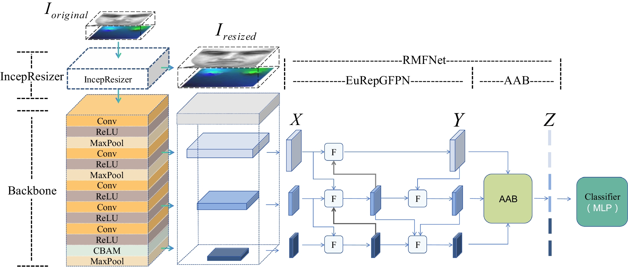
This section enhances the detection of traffic signals and navigation of zebra crossings present considerable difficulties for individuals with visual impairments, particularly in bustling urban settings. Conventional approaches often fall short in providing precision and dependability, especially under conditions of low illumination or when views are obstructed. Fig. 2 illustrates the overall proposed methodology for object detection and zebra crossing.
Fig. 2 The alternative text for this image may have been generated using AI.
Workflow of proposed methodology
This addresses these issues by utilizing advanced DL methodologies, including YOLO11 for object detection, Hough transforms for recognizing crosswalks and CNN for precise identification of traffic signals, thereby facilitating safer navigation.
Data CollectionThe data gathered from the PTL (https://github.com/samuelyu2002/ImVisible?tab=readme-ov-file) is a comprehensive image dataset focused on street intersections, specifically designed for the identification of PTLs and zebra crossings. The dataset includes images that exhibit a range of variations in weather conditions, positioning, and orientation concerning the traffic lights and zebra crossings, as well as differences in the size and type of intersections.
PreprocessingAfter the completion of data collection, preprocessing methods are employed on the collected images to minimize variations in brightness and enhance the contrast of the object and zebra crossing detection. RMSHE is the histogram that is initially divided in a manner akin to Basic Histogram Equalization (BHE). Subsequently, each segment is further divided into two distinct parts in a recursive manner. This process is applied to enhance images of objects and traffic light images using RMSHE is evaluated as in Eq. (1).
where, \(F(X)\) represents the transformation applied to pixel intensity \(X\), \(_\) is the histogram of the input image divided by its average intensity value and \(_\) denotes that the recursive function implements a distinct transformation. Overall, RMSHE enhances the quality of images and readies the data for precise detection and contrast under diverse lighting conditions. After the preprocessing techniques, the image quality expanded, subsequently leading to the traffic sign detection process utilizing the HUNet-MC approach.
Haze U-Net with LeNet Modular Fully CNN for Classifying Traffic SignsThis section describes the HUNet-MC approach to effectively enhance contrast by uniformly redistributing distorted values according to the histogram for the recognition of traffic signs. This approach involves the Haze U-Net in conjunction with a LeNet-based Modular Fully CNN (LeNet-MFCN). The resulting contrast-enhanced feature map consists of three channels. This eliminates haze from the input image [28, 29]. The elimination of haze is frequently grounded in the atmospheric scattering model and is calculated as in Eq. (2).
$$I(y)=K(y)\text\hspace}t(y)+B(1-t(y))$$
(2)
where, \(I(y)\) represents the hazy image, \(K(y)\) denotes the haze-free image,\(B\) signifies the global environment light and \(t(y)\) refers to the communication map, which illustrates the quantity of light that arrives at the camera. Figure 3 represents the process of HUNet-MC for classifying the traffic lights.
Fig. 3 The alternative text for this image may have been generated using AI.
Traffic light classification using HUNet-MC
This collective data serves as the input for the second-stage neural network, ultimately producing a clear image devoid of haze known as the Haze Reduction Module (HRM). Depending on the specific implementation, the Transmission map Estimation Module (TEM) and image contrast enhancement stages are executed concurrently. The outcomes are combined with the contribution of the image and transmitted to the HRM, which efficiently eliminates the haze \(K(y)\) employed as in Eq. (3).
$$K(y)\text}=\frac+B$$
(3)
where, the Haze U-Net model is designed to estimate the transmission map \(t(y)\) and the atmospheric light, \(B\) enabling it to reconstruct a clear image \(K(y)\). The synergy of these two components guarantees precise recognition and localization of traffic signs, even under difficult conditions like low light, haze, or fog. The Histogram of Oriented Gradients (HOG) algorithm is employed to characterize the distribution of image gradients across various orientations, effectively capturing shape and aspect features for the classification of traffic signs as evaluated in Eqs. (4, 5)
$$M(a,b)=\sqrt^_}+^_$$
(4)
$$\theta \text}(a,b)=}^(\frac_}_})$$
(5)
where, \(M(a,b)\) signifies the intensity of the gradient, while \(\theta \text}(a,b)\) indicates the direction of the gradient. LeNet-MFCN generated from vertical strip-pooling is expressed as in Eq. (6).
where the strip-pooled feature maps directions are denoted as \(_^\), respectively. Each of these pooled features is processed through a 1 × 1 convolutional layer that contains 512 filters, which is subsequently followed by a ReLU activation function. The quantity of learnable parameters remains constant, while the receptive field of the filters is expanded by interspersing intermediate kernel values with zeros is as evaluated in Eq. (7).
$$_=\sum_F[j+s.l]*w[l]$$
(7)
where, \(s\) specifies the dilation rate of the kernel with weight \(w\), which is applied to the input tensor \(F\) through convolution. Standard convolution is considered a specific instance of atrous convolution, where the rate \(s\) is set to 1. The gradient orientations are categorized into discrete bins, like nine bins corresponding to the range of 0° to 180°. The voting process for each bin is influenced by the magnitude of the gradient, denoted as \(M(a,b)\) is evaluated in Eq. (8).
where, the weighting function, denoted as \(_(_)\), specifies the extent to which each pixel contributes to the corresponding orientation bin. Subsequently, a Support Vector Machine (SVM) classifier is implemented to eliminate false positives and is evaluated as in Eq. (9).
where, the weight vector is denoted as \(^\), the HOG feature vector is represented by \(y\) and the bias term is indicated by \(a\). In the classification phase, LeNet-MFCN is designed to improve the technique's evaluation, enabling the classification of traffic signs for the identification of VIB into specific categories are calculated using Eq. (10).
$$Y}_=\sum_\sum__.\text}_$$
(10)
where, \(Y\) represents the input image, \(L\) denotes the convolutional kernel and \(Y\) signifies the resulting characteristic map. Finally, predictions are made using the traffic signs identified during the classification phase to evaluate the effectiveness of the prediction of traffic flow signs for VIB in detecting and classifying traffic signs.
Translation Using Text-To-Speech ConverterAfter identifying the traffic signs, the information is transformed into audio signals using a Text-To-Speech (TTS) system. This method vocalizes the names of identified objects to aid visually impaired individuals in effective navigation. The system retrieves the relevant object labels (e.g., "Stop Sign" and "Green Light") from the classification outputs from both LeNet-MFCN and YHTCSCA, and transfers the labels to a TTS engine, such as Google TTS, for audio output. Before the labels are converted, the output contains some text preprocessing, like formatting, context-sensitive messages and removing any unnecessary alerts. After the TTS performs converting the textual labels into intelligible speech, the intelligible speech is relayed to the user through headphones, announcing detected traffic signals and revealing their position on the detected route and instructing navigation. An example is to inform the user with instructions like "For green". The traffic signal is green. You are now allowed to move through the intersection safely." The multimodal feedback provides blind users with opportunities to transfer complex graphic information into functional and practical audio instructions. Speech output is delivered to users in headphones. Thus, Haze U-Net is employed to effectively eliminate haze, thereby improving visibility, while the LeNet-MFCN is responsible for sensing and categorizing traffic signs. Once the classification of the traffic signs is completed, the detection of the zebra crossing is performed using the YHTCSCA approach.
YOLOv11 Hough Line Transform Convolutional Feature-Enhanced Ship Rescue Cross-Attention for Detection of Zebra CrossingThis section introduces the YHTCSCA technique, calculated to assist blind individuals by sensing obstacles and identifying zebra crossings to ensure safe navigation. By employing YOLOv11, the system is capable of recognizing vehicles, pedestrians, and potential dangers, thus offering comprehensive situational awareness.
The functionality of the HLT within the YHTSCA framework acts as a complementary component as it assesses geometrical properties of zebra crossings such as alignment, slope, and spacing of the white stripes; therefore, this two-part system is useful for cases where YOLOv11 detects a zebra crossing incorrectly or fails to detect it at all based on obstructions or fading of the zebra crossing. The HLT improves identification consistency by confirming linear patterns, which help address issues associated with variable conditions. This is proven by producing measurable improvements to detection accuracy or robustness, particularly in settings with low-light or if the visual conditions are cluttered, depending on YOLOv11 or optimizing the HLT integration to sustain computational efficiency. Fig. 4 illustrates the procedure of the YHTCSCA technique.
Fig. 4 The alternative text for this image may have been generated using AI.
Structure of the YHTCSCA method
Furthermore, the CNN Enhanced Cross Attention Mechanism (CNN-ECAM) model, which is trained on labeled images, effectively recognizes zebra crossing patterns across different conditions, thus enhancing safety and accuracy in navigation. The pixels of the image are allocated to the parameter space. First, train spatial features from labeled images, extracting pixels using the convolutional layers of the CNN. Then, apply the cross-attention mechanism. For example, cross-attention strengthens attention to areas like zebra patterns by evaluating the relationships among pixel regions. The pixel data is then mapped to parameter space, where important features, in this case, lines that signify zebra stripes, are identified by some accumulation scores, such as the Hough Transform. This process allows a confident and accurate detection of zebra crossings, regardless of lighting and environmental conditions, thus enhancing navigational safety. In the modified parameter space, lines are subsequently identified using accumulation scores [30,31,32]. The Parallel Spatial Attention (PSA) block enhances the differentiation of spatial features by employing attention mechanisms across multiple spatial scales. The Dilated Spatial Attention (DSA) block effectively models contextual dependencies with dilated convolutions, enabling us to grow the receptive field without growing the number of constraints. The Convolutional Block Attention Module (CBAM) is a simple mechanism that improves the representation of features via channel attention followed by spatial attention. HLT employs the subsequent expression to collect the targets along the specified line is calculated as in Eq. (11).
$$|_-_\text_-_\text\theta |\le \gamma S$$
(11)
where, \(\gamma S\) represents the maximum deviation, which is determined based on the deviations of the targets within the group. The determination of the linearly distributed group targets is expressed in Eqs. (12, 13).
$$ }_:_=_,_,_)\in _\}}^}_$$
(12)
$$ }_:_=_,_,_)\in _\text}or\text}_\}}^}_$$
(13)
where, \( }_\) and \( }_\) denotes the scenarios in which the linearly distributed group targets are used to detect patterns, respectively. To identify each pattern, the detection probability is calculated as in Eq. (14).
$$^_(t)=1-\sum_}_+}_\le 2}q(}^_| }_)\text}q(}^_| }_)$$
(14)
where, \(M\) signifies the total quantity of potential lines within the image, which corresponds to the dimensionality of the parameter space associated with the HLT. Under the condition of \(\widehat\), the distribution becomes more intricate due to the presence of true targets being detected at the zebra linear characteristics of zebra crossings by detecting white stripes and evaluating their alignment and slope. YOLOv11 construction involves three principal elements: the backbone, the neck and the head. The backbone serves as the main feature extractor, employing CNNs to convert the original image into a series of feature maps across various scales, thereby capturing essential structural details. This module is structured with multiple heads. For \(Y\in \text}^\), the associated query \(Q\), key \(K\) and value V are projected accordingly. The Sliding Window Dual Attention (SWDA) module combines dual attention mechanisms through both standard and dilated convolutions within sliding windows, facilitating improved local–global contextual awareness. This module significantly boosts detection accuracy, particularly in scenarios involving occlusion or clutter. The channels of the feature map are segmented into n distinct parts and executed across various heads utilizing different null rates calculated as in Eqs. (15, 16).
$$_=SWDA\text\hspace}(_,\text}_\text},_,_),1\le i\le m$$
(15)
$$Y=Linear\text}(Concat[_,.....,_])$$
(16)
where, \(_\) denotes the output of the SWDA module for the \(i-th\) head, while \(_\) signifies the dilation rate associated with the \(i-th\) head. This emphasizes that \(_(f)\) is calculated through the element-wise summation of the descriptors obtained from both Global Average Pooling (GAP) and Global Max Pooling (GMP), thereby facilitating the information through a multilayer process is evaluated as in Eq. (17).
$$_(f)=\beta \text}[MLP(GAP(f))\oplus \text}MLP(GMP(f))]$$
(17)
where, \(_(f)\) denotes the input characteristic map, \(GAP(f)\) is the process that performs global pooling by calculating the average value across all spatial locations within each feature channel. \(GMP(f)\) is method is akin to GAP, \(\oplus\) is the output from the MLP applied to \(GAP(f)\) and \(GMP(f)\) are concatenated, enabling the model to leverage both average and max-pooled representations and \(\beta\) is a non-linear function. The final output characteristic map is obtained through the element-wise summation of the input feature maps provided as in Eq. (18).
where, \(_\) is the feature representation resulting from the processing stage. \(_\) is the preliminary feature representation before any transformations are applied and \(_\) denotes the enhanced feature representations achieved through a specific transformation, like feature enhancement, attention mechanisms, or residual connections. The transformer demonstrates strong abilities in extracting feature information, allowing it to identify long-range dependencies and gather global contextual insights. Following the acquisition of these tensors, it performs element-wise multiplication to generate improved features \(_\) and \(_\) that have been processed through the attention mechanism and are expressed as in Eqs. (19, 20).
$$_=soft\text(\frac_(KR(_))}__}}})_$$
(19)
$$_=soft\text(\frac_(KR(_))}__}}})_$$
(20)
where, \(__}\) represents the dimension of \(_\), while \(__}\) denotes the dimension of \(_\).The resulting summed features are then processed through a multi-layer perceptron block that employs a residual structure expressed using Eq. (21).
$$D=_[MLP[\text}_\oplus _]]\oplus (_\oplus _)$$
(21)
where, \(MLP\) refers to the multi-layer perceptron, while \(_\) stands for loss function. The architecture of the \(MLP\) primarily consists of two rectilinear layers, disconnected by the Gaussian Error Linear Unit (GELU) stimulation function. This approach helps visually impaired people navigate by detecting obstacles and identifying zebra crossings. Although YOLOv11 excels at identifying zebra crossings, the information varies under the circumstances. There is a possibility that YOLO misclassifies or fails to detect crosswalks in certain scenarios, including faded road markings, low-light conditions, shadows, occlusions, or environments with significant visual clutter. The HLT is not merely a redundant tool; instead, its capability to identify geometric line shapes enables the system to validate YOLO's predictions and ensure that the shapes of the identified crosswalks remain consistent (e.g., parallel stripes) and correctly oriented. This integration minimizes the false positives and false negatives is crucial for applications related to the safety of pedestrian and/or visually impaired navigation for real-time performance. To minimize the loss function parameter, SROA is used as fine-tuning, giving an improved solution to detect obstacles and identify zebra crossings.
Ship Rescue Optimization AlgorithmThis section provides the proposed SROA, which is included in the approaches made to improve the YHTCSCA method's loss parameters. The ship rescue process is divided into two cases: a first case with a known specific spot where the person in distress is located and the second case is a search in a confined area, giving the fastest resolution possible [33].
This initialization of the number of objects and their locations is presented as Eq. (22).
$$_(t+1)=_}+s\times (_}-_})$$
(22)
where, \(t\) represents the iteration time, \(s\) signify a casual number within the range of 0 to 1. The position of the ship \(i\) at the \(t-th\) iteration is indicated by \(_(t)\). Additionally, \(_}\) and \(_}\) denotes the boundaries of the problem for the detection of the objects and the zebra crossing.
The Fitness Function represents the optimization procedure described in Eq. (23). This approach aims to diminish the loss function to improve the detection of objects and zebra crossings.
where, \(F(x)\) denotes the fitness function and \(\text\\) represents the objective of reducing the loss parameter associated with the detection of objects and zebra crossings. Figure 5 presents the main steps involved in the proposed SROA methodology.
Fig. 5 The alternative text for this image may have been generated using AI.
Thus, YHTCSCA significantly improves navigation safety for individuals with visual impairments. This methodology accomplishes its goals by identifying obstacles, recognizing zebra crossings, and assessing potential hazards. Furthermore, it offers reliable situational awareness across diverse environments, significantly improving accessibility and mobility.
The pipeline of RMSHE for preprocessing, U-Net for dehazing, LeNet-MFCN for classification, YOLOv11 for object detection, HLT for geometric analysis, and a CNN-based cross-attention with optimization involves considerable computational complexity and latency. Including the SROA expedites the application while still being cost-effective. The composer SROA optimally modifies crucial parameters throughout the detection and optimization process and efficiently directs search decision-making. This is analogous to establishing priority lines when rescuing people from a disaster. When paired with hardware acceleration and streamlined model variants, SROA optimizes the multi-stage pipeline RMSHE, U-Net, HLT and YHTCSCA, enhancing its responsiveness and practicality for implementation. As a result, the integration of SROA preserves high detection accuracy and reliability and boosts system efficiency, rendering the solution more economical and applicable for real-world scenarios.
Comments (0)