
Remember me
This in vitro study was approved by local Non-Interventional Clinical Research Ethics Committee (Approval No. 2024/115).
Sample size calculationThe sample size was calculated using GPower v3.1 for Macintosh (Heinrich Heine University, Düsseldorf, Germany). An a priori power analysis was performed for the F-test family (ANOVA: fixed effects, omnibus, one-way) based on data from a previous study [18]. With an effect size (f) of 2.35, an alpha error probability of 0.05, and a statistical power (1 − β) of 0.99, a total of 10 specimens per group were determined as the required sample size to detect potential significant differences among groups.
Sample selectionForty-five extracted human maxillary first molars with fully developed apices, intact roots, and without caries, cracks, or previous endodontic treatment were collected from patients who had undergone extractions for periodontal, orthodontic, or prosthetic purposes. The teeth were carefully cleaned of residual soft tissue using a periodontal curette (15/16; Hu-Friedy Co., Chicago, IL, USA) and then preserved in 0.1% thymol solution at 4 °C until further use.
All specimens were initially evaluated using cone-beam computed tomography (CBCT) (I-CAT Vision™, Imaging Sciences International, Hatfield, PA, USA) to assess root canal morphology. Scanning parameters included 120 kV, 5 mA, an exposure time of 8.9 s, and a field of view measuring 16 × 13 cm with a voxel resolution of 0.3 mm. The images were processed using ImageJ software (version 1.36b; National Institutes of Health, Bethesda, MD, USA), and canal curvature was determined following the method described by Schneider [19]. In both mesiodistal (MD) and buccolingual (BL) projections, one line was drawn parallel to the canal axis in the coronal third, and another was extended from the apical foramen. The acute angle formed at their intersection represented the degree of curvature.
Following this assessment, MB roots demonstrating moderate curvature between 10° and 20° and possessing two distinct canals with a Vertucci Type IV configuration were selected [20]. To ensure sample standardization, teeth exhibiting root fractures, incomplete root formation, calcified canals, or apical foramina wider than a #10 K-file were excluded. Consequently, 30 MB roots that met all inclusion criteria were included in the final analysis.
Sample preparationBefore commencing canal instrumentation, morphological comparability among the specimens was confirmed by analyzing the baseline morphometric data of the MB1 and MB2 canals. No statistically significant variations were observed among the groups in canal length, volume, surface area, or structure model index (SMI) (p > 0.05). Likewise, dentin-thickness values measured on the mesial and distal aspects at the furcation level and at 1 mm intervals up to 5 mm showed no significant differences. These results confirmed that all samples exhibited comparable morphologic characteristics and were statistically homogeneous prior to instrumentation (Table 1).
Table 1 Baseline morphometric parameters (mean ± SD) of the mesiobuccal canals (MB1 and MB2) showing homogeneous distribution among groups before instrumentationAfter homogeneity was established, the specimens were randomly divided into three experimental groups according to the NiTi system used for canal preparation: PTU, PTG, and RB (n = 10 MB1 and MB2 canals in each group). Randomization was performed using a computer-generated allocation sequence to ensure unbiased group assignment.
To simulate the periodontal ligament and ensure specimen stabilization during the procedures, each tooth was positioned within a custom acrylic block filled with light-body silicone impression material (Zetaplus, Zhermack SpA, Italy) to maintain standardized positioning and reproducibility throughout canal preparation and micro-CT scanning [21]. Working length (WL) was established 1 mm short of the apical foramen, determined when the tip of a #10 K-file (Dentsply Maillefer, Ballaigues, Switzerland) was visible at the apex.
All instrumentation procedures were performed by a single experienced operator following each manufacturer’s protocol. A VDW Gold Reciproc endodontic motor (VDW, Munich, Germany) was used for both continuous rotation and reciprocating motions. Throughout the shaping process, canals were irrigated with a total of 10 mL of 5.25% sodium hypochlorite (NaOCl) (Promida, manufacturer) and 5 mL of distilled water, delivered with a 30-gauge irrigation needle (Dentsply Sirona, Ballaigues, Switzerland).
ProTaper Ultimate (PTU) groupManual glide path preparation was performed using a #10 K-file in accordance with the standardized protocol applied across all groups. The MB1 and MB2 canals were shaped using the PTU system (Dentsply Sirona, Ballaigues, Switzerland) following the sequence of Slider, Shaper, F1, and F2 instruments. All files were used in continuous rotation at 400 rpm with a torque setting between 4 and 5.2 N·cm, as recommended by the manufacturer [22]. Instrumentation was carried out using gentle brushing motions during withdrawal to preserve the natural curvature of the canals and to promote efficient debris removal until the predetermined working length was reached.
ProTaper Gold (PTG) groupManual glide path preparation was performed using a #10 K-file in accordance with the standardized protocol applied across all groups. Canal preparation in this group was performed using the PTG system (Dentsply Sirona, Ballaigues, Switzerland) in the sequence of S1, S2, F1, and F2 instruments, operated in continuous rotation at 300 rpm. The torque settings were adjusted to approximately 5.1 N·cm for S1, 1.5 N·cm for S2 and F1, and 3.1 N·cm for F2, as specified by the manufacturer [23]. Each file was applied with light brushing movements along the canal walls to maintain the original curvature and minimize the risk of transportation. To prevent instrument fatigue and ensure consistency, each file was used for a single canal only.
Reciproc Blue (RB) groupManual glide path preparation was performed using a #10 K-file in accordance with the standardized protocol applied across all groups. The MB1 and MB2 canals were prepared using a single RB R25 file (25/0.08) (VDW, Munich, Germany) in reciprocating motion with the “Reciproc All” program of the VDW Gold Reciproc motor, as recommended by the manufacturer [24]. The file was used with a gentle in-and-out pecking motion and light apical pressure until the WL was reached.
Each NiTi instrument was strictly used for the preparation of only one canal. Separate instruments were used for MB1 and MB2 canals, even when both canals were present within the same root.
After instrumentation, all canals were rinsed with 5 mL of 17% EDTA (pH 7.4) for 1 min to remove the smear layer, followed by a final flush with 5 mL of distilled water. The canals were then dried with paper points (Dentsply Maillefer, Ballaigues, Switzerland).
Micro-CT analysesAll samples were scanned both before and after instrumentation using a high-resolution micro-computed tomography system (SkyScan 1172, Bruker micro-CT, Kontich, Belgium). The scanning protocol was standardized at 90 kV and 105 µA with a 0.5 mm aluminum filter, a rotation step of 0.6°, and an isotropic voxel size of 16.2 µm. For each specimen, approximately 1,000 axial cross-sectional images were captured in TIFF format. Image reconstruction was carried out using NRecon software (version 1.7.1.1, Bruker micro-CT) applying a 25% beam-hardening correction, a ring artifact correction level of 10, and a smoothing factor of 3.
The pre- and post-instrumentation datasets were aligned using the three-dimensional registration module of DataViewer software (version 1.5.6.2, Bruker micro-CT). Quantitative morphometric analysis was subsequently performed with CTAn software (version 1.17.7.2, Bruker micro-CT).
Transportation and centering abilityWithin the CTAn analysis software, the canal volume (mm3) and surface area (mm2) were measured for each specimen before and after instrumentation, and the percentage increase in canal volume was subsequently calculated.
Canal transportation and centering ability were evaluated at the furcation level (FL) and at 1, 3, and 5 mm from the apical foramen. The 1-, 3-, and 5 mm levels were defined coronally from the apical foramen on the registered datasets. These parameters were determined using the mathematical formulas proposed by Gambill et al. [25]:
$$} = \left( \right) \, - \, \left( \right)$$
$$} = \, \min \left[ \right), \, \left( \right)} \right] \, / \, \max \left[ \right), \, \left( \right)} \right]$$
M1 and D1 refer to the shortest distances between the mesial and distal canal walls and the outer surface of the root before shaping, whereas M2 and D2 denote the corresponding values after shaping.
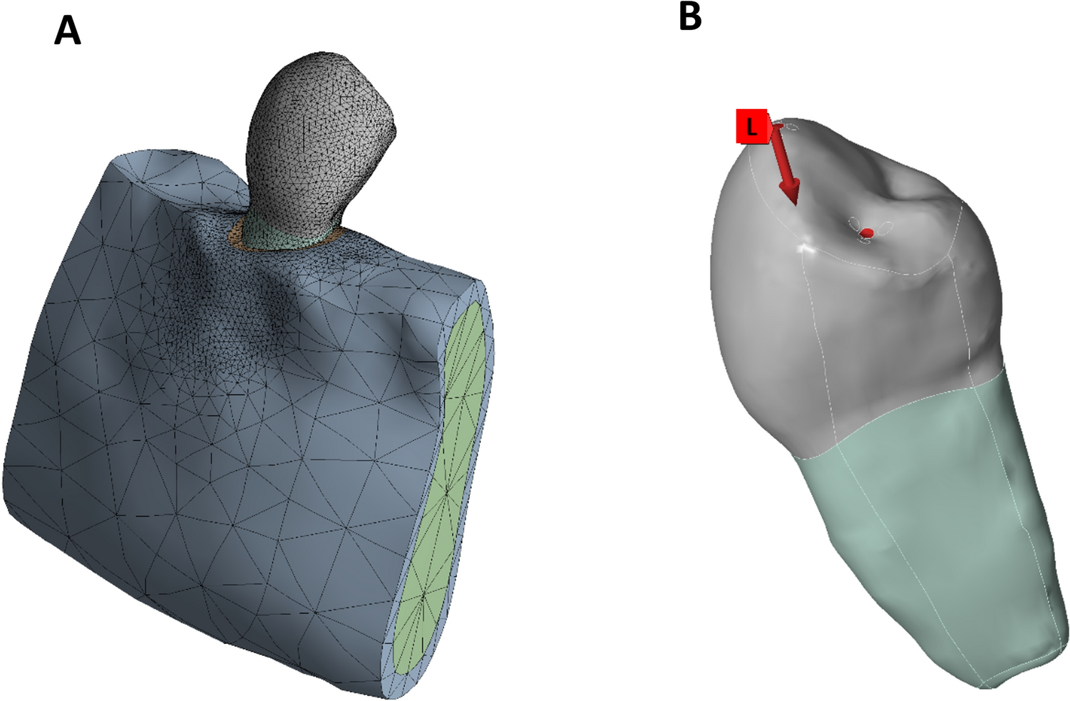
Dentin thickness measurementRemaining dentin thickness was assessed on the mesial and distal aspects of the MB1 and MB2 canals at the furcation level (FL) and at 1, 3, and 5 mm from the apical foramen. The 1-, 3-, and 5 mm levels were defined coronally from the apical foramen on the registered datasets (Fig. 1B). Pre- and post-instrumentation micro-CT datasets were aligned using the three-dimensional registration module to ensure that measurements were taken from identical anatomical locations. At each level, the shortest distance between the canal wall and the external root surface was recorded in millimeters. The amount of dentin removed during shaping was calculated by subtracting post-instrumentation values from the corresponding baseline measurements. All assessments were performed by a single calibrated examiner to maintain measurement consistency.
Fig. 1
A Pre- and post-instrumentation three-dimensional reconstructions of the mesiobuccal root illustrating overall morphological changes. B Axial sections at the furcation level (FL) and at 1, 3, and 5 mm from the apical foramen. Green indicates pre-instrumentation canal boundaries, and red indicates post-instrumentation enlargement. Black arrows indicate areas of dentin reduction, particularly within the distal furcal concavity corresponding to the anatomical danger zone. Representative micro-CT reconstructions of a specimen instrumented with ProTaper Ultimate illustrating measurement methodology and general morphological patterns observed following instrumentation
Complication rateProcedural complications encountered during instrumentation were documented for all specimens. Two parameters were monitored: (1) failure to negotiate the MB2 canal to the established working length and (2) instrument separation. Negotiation failure was defined as the inability to advance a stainless steel #10 K-file or the designated shaping instrument to the full working length following manual glide path preparation. Instrument separation was recorded when any file fractured within the canal during use. Each complication was assigned to the corresponding file system, and the frequency of complications was compared among the groups.
Statistical analysisAll dimensional data were recorded in millimeters and analyzed by a single calibrated examiner. To verify intra-examiner reliability, 20% of the samples were remeasured after a 2 week interval, and the reproducibility of the repeated measurements was statistically confirmed. All data were analyzed using IBM SPSS Statistics v26.0 (IBM Corp., Armonk, NY, USA). Normality was verified with the Shapiro–Wilk test (p > 0.05 for all variables); therefore, group comparisons were conducted with one-way ANOVA, followed by Tukey’s HSD for pairwise tests. Homogeneity of variances was checked with Levene’s test. Statistical significance was set at α = 0.05.
Comments (0)