
Remember me

We give an analysis of the modelling error incurred by using the existing NeRF implementations in the MIS context. We then propose the MIS-NeRF architecture to fix these errors using an appropriate model.
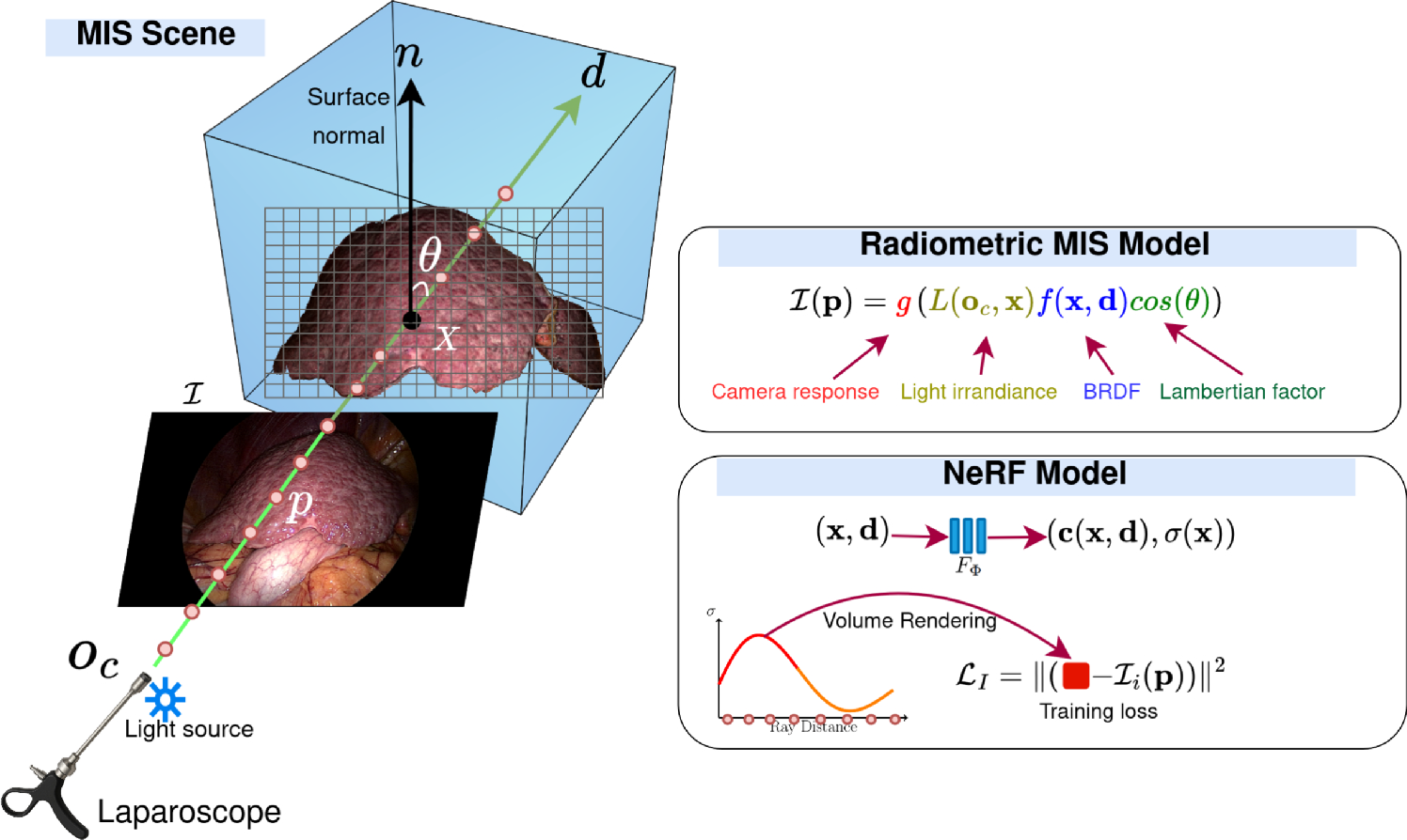
Modelling-error analysisThe challenging MIS conditions often cause reconstruction errors, owing to the modelling approximations in the original NeRF formulation. We identify two challenges. 1) MIS radiometric modelling. In NeRF, the radiance field is sampled along a ray to render the pixel colour, potentially learning elements of the radiometric model including the BRDF and the Lambertian factor. However, the dependency on the camera origin \(\textbf_c\) of the radiometric model, as shown in equation (1), cannot be learnt from the input parameters, leading to errors when attempting to fit the training RGB images. This propagates errors into the density distribution \(\sigma \) and affects the geometry of the reconstructed scene. 2) High-frequency density errors. NeRF reconstructions in MIS exhibit high-frequency surface errors despite accurate RGB rendering. We observed that this is due to three main factors. First, the large textureless areas in the organs, which create ambiguities in the learnt density distribution \(\sigma \). Second, the moist shiny surfaces, which produce specular highlights where the surface normal \(\textbf\) and light ray \(\textbf\) align, resulting in white, saturated areas. While NeRF can reproduce highlights, the \(\sigma \) distribution at these points is ill-defined, leading to bumps and holes in the surface. Third, the limited motion range of the MIS camera, as constrained by the organ and keyhole, creates a small baseline complicating the learning of scene geometry.
The proposed MIS-NeRF addresses both challenges using a radiance model with an explicit spotlight and saturated camera response, and a surface smoothing prior.
MIS-NeRF architectureMIS-NeRF introduces two architectural changes to NeRF: first, it adds \(\textbf_c\) as an input to the field network, and second, it replaces the sigmoid output layer with a ReLU function, modifying the volume rendering equation to account for camera saturation. MIS-NeRF introduces two changes to the NeRF loss function: first, it detects and removes specular highlights, and second, it incorporates depth smoothing into a compound loss. We describe these improvements directly below.
MIS-NeRF field functionThe base architecture of MIS-NeRF is inspired by Nerfacto [17]. Following section 2.1, MIS-NeRF adds the camera origin \(\textbf_c\) as extra input to model light attenuation as:
$$\begin \left( \textbf(\textbf,\textbf,\textbf_c \right) ,\sigma (\textbf))=F_ (\textbf,\textbf,\textbf_c). \end$$
(7)
Function \(F_\Phi \) is represented by several encoders and two MLP blocks, as shown in Fig. 2. A hash encoding is used for the position \(\textbf\), followed by a first small-scale MLP to generate \(\sigma \). A spherical harmonics encoding is used for the ray direction \(\textbf\) and a positional encoding is used for the camera centre \(\textbf_c\), which are both fed into a second MLP, along with the internal embedding from the first MLP, to produce the colour density output \(\textbf\).
We change the sigmoid output layer for the colour density \(\textbf\) to a ReLU, which clips the intensity from the bottom but allows it to overflow from the top. At this stage indeed, the physical irradiance must be positive, but should not be bounded to a particular energy upper-bound. Only at the end of rendering should the irradiance be upper-bounded, which physically occurs owing to the camera sensor saturating in over-exposed pixels. We explicitly model this saturation by adding the post-rendering \(\tanh \) function.
Fig. 3
Proposed registration method using MIS-NeRF and ICP
Volume rendering with camera saturationFollowing section 3.2.1, the proposed MIS-NeRF field function removes saturation from the field equation. For that, we change the existing sigmoid output activation, used in existing implementations, by the unbounded ReLU function. We then explicitly model and incorporate the tanh saturation model described in equation 3, to the rendering equation as:
$$\begin \textbf(r)=\tanh \left( \int _^ T(t)\; \sigma (\textbf(t)) \; \textbf(\textbf(t),\textbf,\textbf_c)\; \textrmt \right) . \end$$
(8)
These modifications allow the camera gain and gamma correction to be learnt by the neural network representing \(\textbf\). They thus allow the colour and density distributions to produce high-intensity colours for each ray without explicitly handling saturation. Experimental results reveal that these modifications improve the results of the original NeRF architecture in MIS conditions, enabling the system to better learn and reconstruct the structure of the scene around saturated areas. This is for instance clearly visible in the reconstructed images shown in Figs. 5 and 6.
Training lossWe train MIS-NeRF using a compound loss \(\mathcal _T = \mathcal _I + \lambda \mathcal _s\). The colour-error term \(\mathcal _I\) is defined in equation (6) and the smoothing term \(\mathcal _s\) is:
$$\begin \mathcal _s= & \sum ^_\sum _\in \Omega _i} \left( |D(\textbf_i(\textbf))-D(\textbf_i(\textbf+\mathbf ))|\right. \nonumber \\ & \left. +|D(\textbf_i(\textbf))-D(\textbf_i(\textbf+\mathbf ))| \right) , \end$$
(9)
where \(\textbf_i(\textbf)\) is the ray corresponding to pixel \(\textbf\) in the i-th camera, and \(D(\textbf)\) represents the depth synthesised by the MIS-NeRF MLP. The pixel displacements \(\mathbf \) and \(\mathbf \) represent the 4-neighbour pixel rays.
In MIS-NeRF, saturated highlight areas are removed from the region \(\Omega _i\), improving surface reconstruction and enabling automatic highlight inpainting when synthesising new views. MIS-NeRF fills in these areas using information from the other images where the area shows diffuse reflection. In our experiments, we used the segment anything model (SAM) [18] for foreground masking and segmented the highlights with simple intensity thresholding.
Fig. 4
(top) MIS images and number of frames in each dataset. (bottom) preoperative 3D models with deformation heat maps shown for Synth-NR1 and Synth-NR2
Comments (0)