
Remember me
All materials’ specification, compositions, and manufacturers are summarized in Table 1.
Table 1 Materials’ specification, compositions, manufacturers, and LOT numbersSample size calculationA power analysis was conducted to ensure sufficient statistical power for testing the null hypothesis that there is no difference in fracture resistance among various forms and amounts of cusp reduction in CAD/CAM composite blocks used in maxillary permanent premolars. An alpha level of 0.05 and a beta level of 0.2 (i.e., 80% power) were adopted, with an effect size of 1.28, calculated based on the findings of Alassar et al. [6]. The estimated required sample size was 33. To account for potential sample loss during testing, the sample size was increased by 30%, resulting in a final sample size of 42. The calculation was performed using G*Power software version 3.1.9 (Heinrich-Heine University, Düsseldorf, Germany).
Teeth selectionThe study was conducted after approval of the committee of ethics at the faculty of dentistry at the British University in Egypt (approval no. 21-023). Premolars were obtained from an Egyptian population with an age range of 16–25 years admitted to the oral and maxillofacial surgery department at the British university in Egypt. A total of 42 sound human first maxillary premolars freshly extracted for orthodontic treatment were selected. All patients approved their extracted teeth to be used in research and signed a consent explaining this. The teeth were evaluated to ensure anatomical uniformity in terms of crown length, as well as mesiodistal (7 ± 0.5 mm) and buccolingual (8 ± 0.5 mm) dimensions [15]. All dimensional were measured at the proximal cementoenamel junction using a digital caliper (Bacolis Digital Clipper, Stainless Hardened, Generic, China). Immediately following extraction, the teeth were cleaned, disinfected [16], and examined under magnification to ensure they were free of caries, cracks, or hypoplastic defects. Any teeth showing such defects were excluded and replaced. The selected specimens were stored in glass jars containing distilled water at 4 °C and used within 3 months [17]. The distilled water was refreshed every 5 days until the experiment commenced.
Preparation of specimens and cavity preparationEach tooth was fixed in cold-cured acryl (Acrostone, Cairo, Egypt) that was applied in plastic cylinders (3 cm × 2 cm). For periodontal ligament simulation, the roots of all specimens were covered by molten wax (Renfert GEO Classic, Hilzingen, Germany) to form a 0.2 mm to 0.3 mm film [18]. Then the teeth were implanted in an auto-polymerizing acrylic resin vertically till 2 mm below the C.E.J [13] while being in the soft dough stage. A centralizing device was used to ensure that the teeth were positioned with their long axis perpendicular to the base of the cylinder. The wax film was carefully removed by hot water and a wax blade. Light-body polyether impression material was then injected (Elite HD + , Zhermack, Rovigo Italy) into the obtained space and teeth were replaced in the block allowing the light body to set [19].
Standardized MOD preparations in all teeth without gingival seats. The cavity was prepared using a high-speed air–water cooling handpiece and #4261 inlay preparation kit (Komet Inlay preparation Kit, Brasseler, GmbH, Germany). Abrasives were replaced every four times of use. The prepared cavities had a depth of four millimeters measured from the buccal cusp tip as a reference point and a width of 3 mm representing one-half the inter-cuspal distance. This was measured using a periodontal probe and verified using a digital caliper (Fig. 1). To ensure standardization and repeatability of preparations, all preparations were done by the same operator.
Fig. 1
Groups I, II and III (a) MOD cavity depth 4 mm by periodontal probe, (b) MOD cavity depth 4 mm by digital clipper, (c) MOD cavity width 3 mm by periodontal probe, (d) MOD cavity width 3 mm by digital clipper
Grouping of specimensRandom distribution of teeth was done according to the form of cusp reduction into three main groups (n = 14); G1:MOD cavities restored with inlays without cusp preparation, G2:MOD cavities restored with overlays with buccal and palatal anatomical cusps reduction (Fig. 2), G3; MOD cavities restored with overlays with buccal and palatal flat cusps reduction (Fig. 3). Groups 2 and 3 were further sub-divided into two sub-groups (n = 7) according to the amount of cusp reduction to be either 1.5 mm or 2.5 mm of cusps reduction.
Fig. 2
(a) Group IIa anatomical cusp reduction of 1.5 mm with remaining cavity depth 2.5 mm, (b) Group IIb anatomical cusp reduction of 2.5 with remaining cavity depth 1.5 mm
Fig. 3
(a) Group IIIa flat cusp reduction of 1.5 mm with remaining cavity depth 2.5 mm, (b) Group IIIb flat cusp reduction of 2.5 mm with remaining cavity depth 1.5 mm
Construction of CAD/CAM composite restorationsAll prepared specimens were scanned using the Omnicam intra-oral scanner integrated with the CEREC system (CEREC SW5, Dentsply Sirona) to capture digital impressions [15]. The scanning duration was ranged from 25 to 35 s for all specimens for standardization. The optical impressions were tested to avoid improper images that would affect the accuracy of the final restorations and then sent to the lab for designing. The design of the restorations was done using Exocad (Exocad, Darmstadt, Germany). The thickness of all restorations was standardized by the software. After designing the restoration, the margins, anatomy and contour were checked. The selected composite blocks were inserted in the milling machine (MC X5, Dentsply Sirona) and fixed with the set screw then milled and checked for accuracy and seating on their specimens. All specimens were polished in accordance with the manufacturer's guidelines using a Vita Enamic kit (VITA Zahnfabrik, Bad Säckingen, Germany), beginning with the coarsest grit tips and progressing to the finest.
Pretreatment of CAD/CAM composite restorations before cementation (Fig. 4)Fig. 4
(a) Sandblasting using Aquacare dental air abrasion, (b) silane coupling agent, (c) universal adhesive prime and bond, (d) Light curing using light-emitting diode (LED)
The fitting surfaces of the final composite restorations underwent the following treatment: they were aluminablasted for 20 s using 29 µm aluminum oxide particles at an air pressure of 0.2 MPa [20], employing an Aquacare Twin Dental air abrasion unit (Velopex Int, Medivance Instruments, London, UK). After aluminablasting, the restorations were cleansed in an ultrasonication unit for 2 min, then rinsed for 20 s and dried by air for 10 s. A silane coupling agent was applied and left in place for 1 min before being air-dried [21]. Subsequently, a slim film of universal adhesive (Prime & Bond Universal, Dentsply Sirona, USA) was actively applied using a 1.5 mm green fine-type micro-brush (Easyinsmile, Passaic, New Jersey, USA) and left undisturbed for 20 s. The adhesive was then air-thinned for 10 s and cured for 20 s with an LED polymerization device at a light irradiance of 1470 mW/cm2 ± 10%, tip diameter of 10 mm and a single, high-intensity continuous curing mode (3 M ELIPAR DEEPCURE, L1007-240 V INT, St. Paul, MN, USA).
Pretreatment of prepared cavity before cementationA selective etch protocol was employed using the universal adhesive following the manufacturer’s recommendations. The enamel margins of the cavities were selectively etched with 37% phosphoric acid gel (FineEtch 37%, Spident, Gojan-dong, Namdong-gu, Incheon, South Korea) for 20 s, followed by rinsing by air/water spray for 20 s, and finally drying with air for 5 s. Followed by application of generous coat of the universal adhesive prime and bond, the adhesive was actively rubbed on both enamel and dentin by a micro-brush (Easyinsmile, Passaic, New Jersey, USA) for 20 s then air thinning for 10 s and polymerized by for 20 s using the same curing unit.
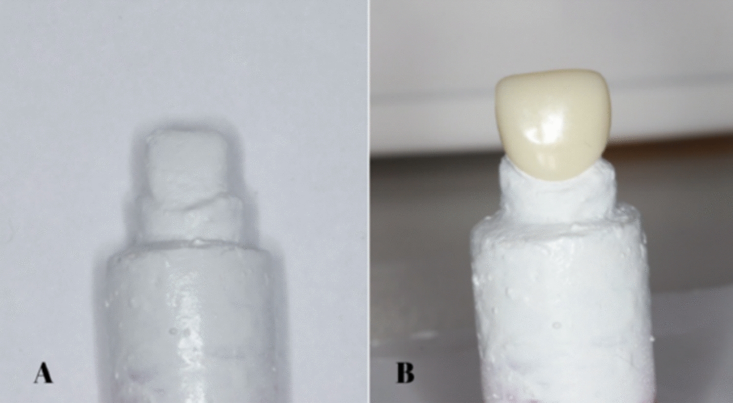
Luting procedure (Fig. 5)Fig. 5
(a) Thin layer of the self-adhesive dual-cure resin cement, (b) CAD/CAM composite restoration placed with gentle finger pressure, (c) Polymerization using LED light curing unit
A thin layer of self-adhesive dual-cure luting resin (Calibra Universal, Dentsply Sirona) was applied to the surface of each pretreated cavity. Each CAD/CAM composite restoration was then positioned onto its corresponding cavity using gentle finger pressure, applied consistently by the same operator for all specimens. Excess resin was immediately removed using a micro-brush, and the tooth-restoration interface were coated with glycerin gel to serve as an air-blocking agent and prevent oxygen inhibition of the luting resin, ensuring complete curing. The luting resin was cured using the similar curing unit for 20 s from all directions. Once polymerization was complete, the gel was washed by air–water spray.
Storage of specimens and thermocyclingStorage of all specimens in distilled water at room temperature for 24 h was done before thermocycling and fracture resistance testing. The cemented restorations were thermally cycled in distilled water for 5000 cycles at 5 ± 2 °C/55 ± 2 °C, with a 50 s dwell time and 10 s transfer time using a thermocycling device (SD Mechatronik Thermocycling, Julaba, Germany).
Fracture resistance testing and failure mode evaluationAll specimens underwent fracture resistance testing using a Universal Testing Machine (Instron, Model 3345, Buckinghamshire, UK) [22]. Each specimen's acrylic block was fixed to the lower head of machine, while a continuous static load was applied to the crown using a five mm diameter stainless-steel ball attached to the upper movable head. The load was applied in an axial direction at a crosshead speed of 1.0 mm/min until failure occurred. The force required to induce failure (measured in Newton) was recorded using the machine’s software (Blue Hill Universal, Instron). Following fracture testing, the broken specimens were examined under a stereomicroscope (Nikon MA 100, Minato, Japan) to determine the mode of fracture. The fractures were categorized according to the following failure patterns: Type I: isolated fracture of the restoration; Type II: fracture involving a small portion of the tooth; Type III: fracture involving half of the tooth above the cementoenamel junction (CEJ); Type IV: fracture extending below the CEJ.
Statistical analysisCategorical data were expressed as frequencies and percentages and analyzed using the chi-square test. Numerical data were reported as means with 95% confidence intervals, standard deviations, and minimum and maximum values. Normality and homogeneity of variances were assessed using the Shapiro–Wilk and Levene's tests, respectively. While the data followed a normal distribution, the assumption of equal variances was not met. Therefore, Welch’s one-way ANOVA was applied, followed by the Games–Howell post hoc test. A significance threshold of p < 0.05 was used for all statistical tests. Analyses were conducted using R version 4.3.1 for Windows (R Core Team, 2023. R: A language and environment for statistical computing. R Foundation for Statistical Computing, Vienna, Austria. https://www.R-project.org/).
Comments (0)