
Remember me
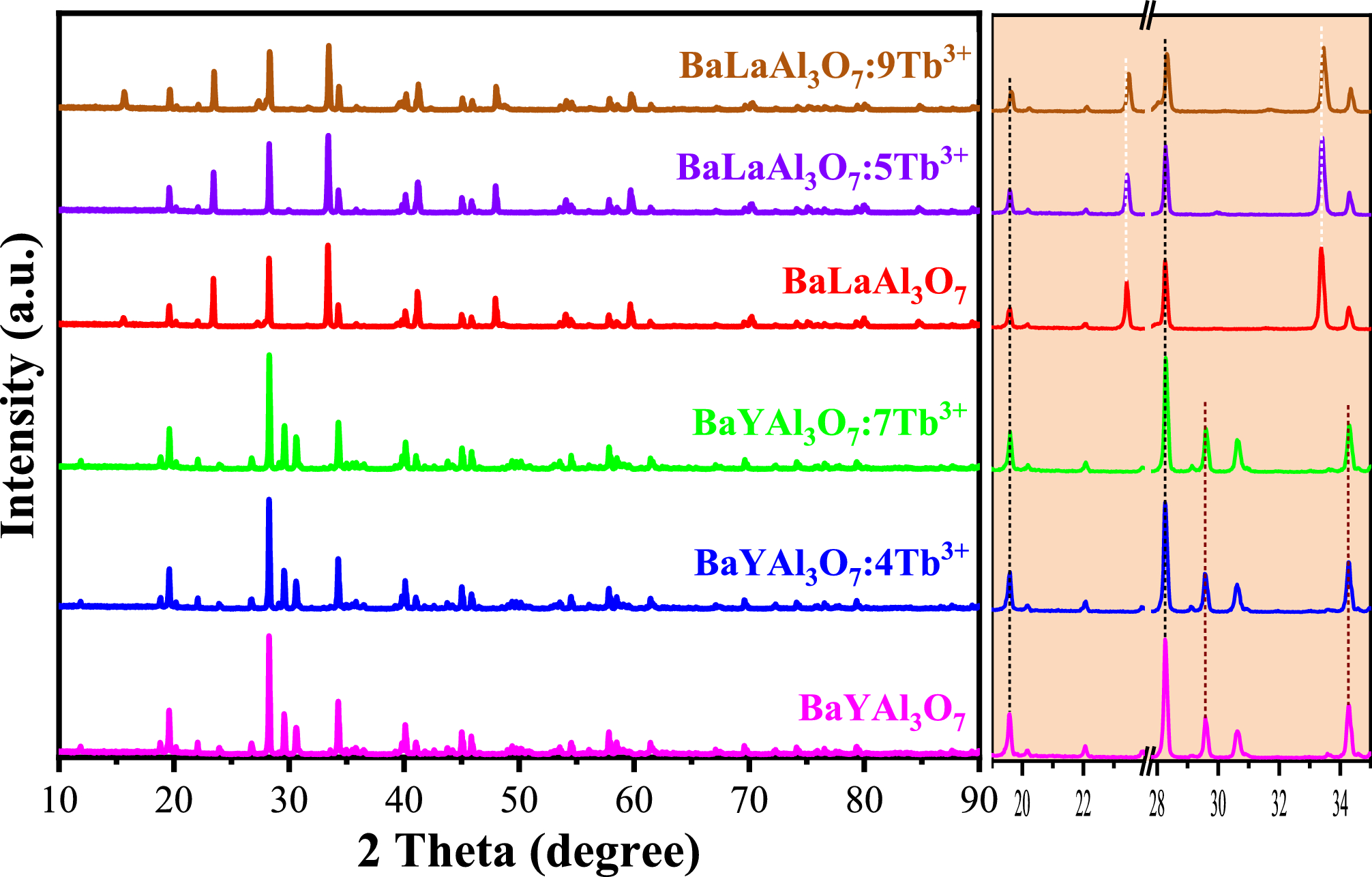
The conceptual configuration of the proposed thin-form-factor laser scanning system is shown in Fig. 1. The scanning system primarily consists of a laser source and an MEMS mirror. The laser source is a planar type and comprises three RGB laser diodes (LDs) and a waveguide-type combiner [22]. The combined RGB laser beams emitted from the laser source are aligned along the same axis and parallel to the substrate. The MEMS mirror is also planar and is formed on a MEMS substrate made of silicon (Si), with its surface parallel to the substrate. A notable feature of the laser scanning system is that the laser source and MEMS mirror are mounted on the same common substrate, as shown in Fig. 1. This configuration enables a laser scanning system with a thin and small form factor.
Fig. 1
Conceptional configuration of the proposed thin-form-factor laser scanning system
In this system, although the laser beams are parallel to the MEMS mirror surface, the combined laser beams should be incident on the MEMS mirror with high efficiency. Therefore, a beam-deflection module is required. The system is designed to emit scanning laser beams in three directions: (1) reverse, (2) perpendicular, and (3) forward relative to the combined incident beams, as illustrated in Fig. 1. Consequently, the beam-deflection module must support these functionalities while also ensuring that the beam is effectively incident on the MEMS mirror surface.
Figure 2a shows the overall layout of the actual system. The RGB combined beams emitted from the laser source pass through the collimating lens, forming collimated beams that enter the beam-deflection module. In this design, the module is detachable. The beams are then reflected by the MEMS mirror and emitted in different directions by replacing the beam-deflection module.
Fig. 2
Actual layout of the thin-form-factor laser scanning system: a overall layout (side view); b schematic of the detachable beam-deflection module (side view). Here, (1) simple mirror, (2) beam splitter, and (3) prism mirror types
A schematic of each detachable beam-deflection module is shown in Fig. 2b. The simple mirror, beam splitter, and prism mirror types, as labeled in the figure, correspond to (1) reverse, (2) perpendicular, and (3) forward directions relative to the incident combined beams, respectively. In the simple mirror type, the incident beam is first reflected by a flat mirror and then by the MEMS mirror, forming a two-dimensional scanning beam. In the beam splitter type, the incident beam is reflected by the half mirror, then normally incident on and reflected by the MEMS mirror, and finally passes through the half mirror again. Therefore, the overall beam power is reduced by a quarter. In the prism mirror type, the incident beam is reflected by the first prism surface, then by the MEMS mirror, and finally by the second prism surface. Consequently, the surface area of the second prism must be larger than that of the first prism. This is because the laser beam after scanning must hit the surface of the prism.
2.2 Analysis of the projection image distortionThe angle of incidence on the MEMS mirror surface is another critical factor for achieving high-quality, undistorted laser projection images. Typically, two-dimensional scanning using a MEMS mirror introduces distortions in the laser projection image [23, 24]. Although such distortions can be corrected using image-rendering software, spatial corrections lead to unnecessary dead space and reduce the area of the effective laser projection image. Therefore, the incident angle must be optimized to construct a high-quality laser scanning system.
The distortion of the projection image can be analyzed using the x-, y-, and z-coordinates for the incident beam reflection by the MEMS mirror, as shown in Fig. 3. In this analysis, a raster scan is assumed. Therefore, the x-axis represents the rotation axis for vertical slow scanning; the y-axis represents the rotation axis for horizontal fast scanning; and the z-axis represents the direction normal to the mirror surface. In this case, two reflection configurations were considered: an incident beam (a) in the x–z plane and (b) in the y–z plane. Thus, considering in Fig. 2, the scan along the paper plane corresponds to a horizontal fast scan in case (a) and a vertical slow scan in case (b). For an incident beam in the x–z plane (Fig. 3a), the reflection direction \(s_\) of the incident laser beam \(s_\) is described as follows:
$$s_ = s_ - 2\left( } \right)n,$$
(1)
where \(}\) is the normal vector of the mirror surface and \(}}_}}}\) and \(}\) are expressed as
$$}}_}}}=\left[\begin-\text(_)\\ 0\\ -\text_)\end\right],$$
(2)
$$}=\left[\begin_\\ _\\ _\end\right]=\left[\begin\text(_)\\ -\text(_)\text_)\\ \text_)\text_)\end\right],$$
(3)
where \(_\) is the angle between the incident beam and z-axis, \(_\) is a mirror rotation angle around the rotation axis for horizontal fast scanning, and \(_\) is a mirror rotation angle around the rotation axis for vertical slow scanning.
Fig. 3
Coordinate systems for incident beam reflection by the MEMS mirror. Incident beam in the a x–z plane and b y–z plane
For convenience, the actual rotation angle can be expressed using an alternative coordinate system, in which the beam reflected from the stationary MEMS mirror surface lies along the z-axis. This new coordinate system is defined by rotating the original fixed coordinate system by \(-_\) around the y-axis. In this coordinate system, the reflection direction \(s_\) in the new coordinate system is described as follows:
where
$$M = \left[ c} )} & 0 & } \right)} \\ 0 & 1 & 0 \\ } \right)} & 0 & )} \\ \end } \right].$$
(5)
Hence, the reflection angle \(_\) for the horizontal fast scan and the reflection angle \(_\) for the vertical slow scan are respectively derived as
$$_=}^\left(}}_}}}}}^}}/}}_}}}}}^}}\right),$$
(6)
and
$$_=}^\left(}}_}}}}}^}}/}}_}}}}}^}}\right).$$
(7)
On the other hand, when the incident beam is in the y–z plane as shown in Fig. 3b, Eqs. (8) and (9) are used instead of Eqs. (2) and (5), respectively.
$$}}_}}}=\left[\begin0\\ -\text(_)\\ -\text_)\end\right],$$
(8)
$$}=\left[\begin1& 0& 0\\ 0& \text_)& \text(_)\\ 0& -\text(_)& \text_)\end\right].$$
(9)
Figure 4 illustrates the distortion of the laser projection image calculated using the equations described above. The distortions for the three incident angles \(_\) of 32°, 0°, and 34° are shown. These angles correspond to the fabricated detachable beam-deflection modules. The horizontal scan angle was ± 24°, and the vertical scan angle was ± 13°, matching the optical scan angle of the MEMS mirror used for fabrication. As shown in Fig. 4, the original beam-deflected positions, represented by blue squares, are distorted to the actual deflected positions represented by orange circles. This distortion is evident in both cases of incident beams in the x–z plane (a) and y–z plane (b). The distortion in the vertical scan angle is greater than that in the horizontal scan angle for (a) an incident beam in the x–z plane, whereas the opposite is true for (b) an incident beam in the y–z plane.
Fig. 4
Calculated distortion mapping of the laser projection image for incident beam in the a x–z and b y–z planes. The distortions of the incident angles \(_\) for (1) 32°, (2) 0°, and (3) 34°; blue square: original position; orange circle: calculated scanned position
Figure 5 provides further insight into these distortion behaviors by showing the amount of distortion, defined as δH = (Hmax\(-\) Hmin)/H0 for horizontal fast-scan direction and δV = (Vmax\(-\) Vmin)/V0 for vertical slow-scan direction. Here, Hmax, Hmin, and H0 are the maximum, minimum, and center widths of the projection image in the horizontal fast-scan direction, respectively, whereas Vmax, Vmin, and V0 are the maximum, minimum, and center widths of the projection image in the vertical slow-scan direction, respectively. The definitions of these values are presented in Fig. 4 (1). Figure 5 confirms the difference in the amount of distortion between the horizontal and vertical scan angles for both the incident beam in the (a) x–z plane and (b) y–z plane. The difference is as large as two orders of magnitude. Moreover, when the incident angle exceeds approximately 45°, the distortion increases significantly for both the horizontal distortion in (b) and vertical distortion in (a), as indicated by a comparison with the straight guidelines (red dotted) added in the figure. Additionally, the image span in the horizontal fast-scan direction corresponds to the lateral field-of-view (FOV) of the projection image, which is generally expected to be larger. Therefore, we adopted configuration (a), in which the reduction in the horizontal span stemming from the distortion is significantly smaller than that in configuration (b). Thus, configuration (a) with a small incident angle \(_\) of less than 45° was adopted.
Fig. 5
Relation between the projection image distortion and incident angles \(_\) for (1) horizontal fast-scan and (2) vertical slow-scan directions for incident beam in the a x–z and b y–z planes. The red dotted line is to facilitate the understanding of rapid distortion increase
Comments (0)