
Remember me
The dataset used to develop the registration algorithm includes over 200 histological specimens from a breast cancer cohort. All slides were initially stained with standard H&E and digitized using five different scanners from 3DHISTECH (Budapest, Hungary), Hamamatsu Photonics (Hamamatsu, Japan) and Leica Biosystems (Wetzlar, Germany) at three different research centers. A 3DHistech P1000 scanner was used to acquire WSIs at 80× magnification, while the other four devices were used for scans at 40x. Subsequently, these slides were re-stained with an immunohistochemical (IHC) stain for phospho-histone H3 (PHH3) and re-scanned with the P1000 at 80x.
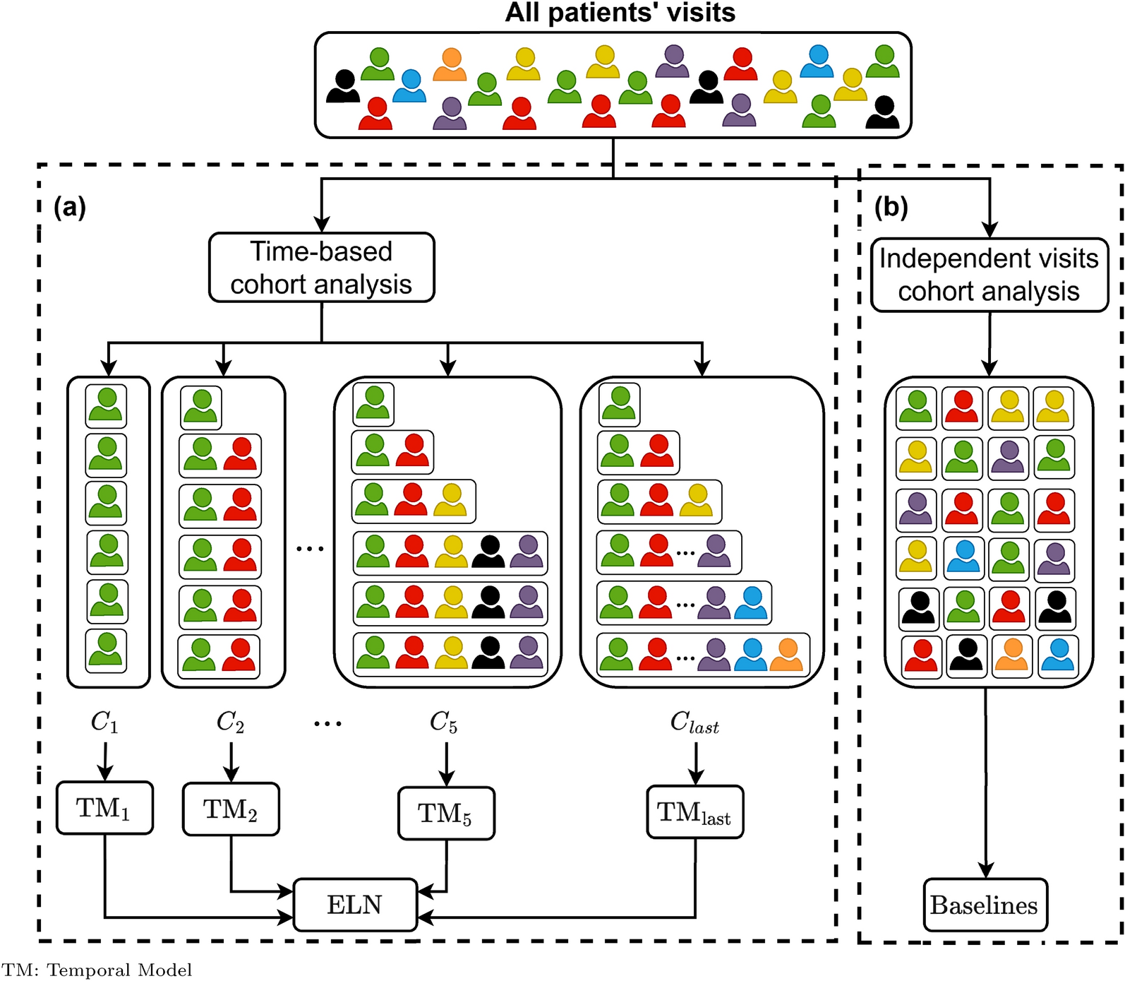
There are several known challenges when working with WSIs. Guerrero et al. [12] have subdivided these into three categories: biological variation, technological variation, and pathological variation. Of these, the technical aspects are particularly important for image registration of histopathological slide sections. These tend to occur during the preparation of histological sections, i.e., artifacts such as tissue folds, tears, or even differences in staining intensities, and are further exacerbated in the image acquisition process. Another class of problems arises in the context of digitization, where, for example, blurring, illumination, and contrast problems may arise [13]. Beyond these obvious and identifiable artifacts, there may be other digitization problems that only become relevant when working with images from different WSI scanners. Indeed, there can be significant differences between WSIs generated from the same histological slide but using different scanners. Three of the main differences between the scanners are shown in Fig. 1.
Fig. 1
Varying WSI appearance between five scanners, depending on the specific device and manufacturer
Depending on the scanner, the visual appearance of WSIs can vary significantly in intensity and coloration. Since these differences are not equally prominent for all tissue structures present, the possibilities of intensity-based registration are already limited. Given that scanners of different manufacturers produce WSIs with varying base coordinate systems and initial orientations, it is a crucial step to address this initial displacement prior to the actual registration process to avoid unnecessarily complicating the optimization of the transformation. However, a more severe problem arises from the preprocessed, automated tissue segmentation of the scanner devices used to determine the area to be scanned. When scanning IHC sections, brighter areas with only a few to no darker signals (e.g., stained nuclei) may be incorrectly classified as background and therefore not scanned. This problem also occurs in HE slides, particularly in areas with a lot of fatty tissue, which have poor contrast to the background. Furthermore, scratches, dust, or other contamination can cause a larger area of the slide to be scanned. If this area differs between several WSIs of the same section, this must also be intercepted during registration.
Despite the same magnification on four of the five scanners, the resolution of the WSIs varies between scanners, with the largest difference being between the Hamamatsu XR at 0.2272 mpp (micrometer per pixel) and the 3DHISTECH P150 at 0.2744 mpp (see Table 1), resulting in structures appearing roughly 20% larger on the P150.
Table 1 Final WSI resolutions in the datasetThis shows that scaling for inter-scanner registration is inevitable, even when the same tissue is scanned at the same magnification level. On the scanned slide sections, 8334 mitoses were annotated in selected tumor regions on H&E WSIs (scanned by a 3DHISTECH P1000 with 40× magnification) and 2533 mitosis on the PHH3 WSIs (scanned by a 3DHISTECH P1000 with 80× magnification).
Much more striking morphological differences may occur between different stains. In standard H&E staining, for example, the cell nuclei are highlighted by the blueish hematoxylin. In IHC stains, hematoxylin is the usual counterstain to the brownish Diaminobenzidine (DAB) chromogen that labels the specific antigen of interest. Therefore, even when re-staining a slide, the DAB may bind beyond the edge of the nucleus and cause a change in the visual appearance of that same morphological structure. Furthermore, the process of re-staining a slide can lead to further deformations. In this process, antigen unmasking steps, such as microwaving or citric acid treatment, may cause part of the tissue to be washed off the slide. However, more frequently, minor deformations, such as tears or tissue displacement, resulting from the mechanical treatment of the slide are the consequence (see Fig. 2).
Fig. 2
Minor tissue deformations occurring when the original H&E slide (left) is re-stained for PHH3 (right)
ConceptBased on the available dataset and the observations made during the manual and automatic digitization of the slide sections, we searched for a novel registration method to generate valid point or annotation mappings from one coordinate system of a reference image I_F, called fixed image to another coordinate system of a corresponding image I_M, namely moving image. In this context, the base layer of a WSI represents the actual image data scanned with the maximum magnification. Since the image data on this base layer usually exceeds common image data sizes and thus usual memory capacities, we have to resort to a hierarchical tile-based approach, both for accessing the image data and for image registration and transformation. Reading and viewing WSIs is mostly implemented in a pyramid-shaped form containing different levels of resolution of the base image, usually sampled down as powers of two, as is done by most slide scanner vendors [14]. Most registration frameworks support multi-resolution strategies that process images from coarse to fine resolution. Still, these cannot be easily applied to images with the dimensions mentioned above, as this would consume considerable memory resources. However, we can take advantage of this strategy by combining the hierarchical approach with a tile-based method on the base layer or a respective level with a similar detailed resolution. This requires a multi-staged registration, starting with a coarse alignment of the whole tissue fragment on a downsampled magnification level (for instance, with a 5× magnification), resulting in an initial transformation that gives a good first estimated alignment of the depicted objects. Crucial for this step, however, is an initial segmentation and detection of the scanned region on which the specimen is located. As mentioned earlier, the actual scanned area of the slide can vary dramatically from scanner to scanner due to internal detection algorithms or configuration profiles. To compensate for these discrepancies, a pre-segmentation is applied before the coarse registration is performed. If the automated segmentation fails and the desired results are far off, the tooling should allow subsequent manual adjustment of the recognized image region. Since the area to be aligned with should be kept as small as possible, the region of interest (ROI) should be tightly bound to the relevant object’s shape. The overview images of these regions will then serve as input images for the initial coarse registration, whereby the respective resolution level is dependent on the magnification of the particular slide scans. This means that for a slide scanned at 80× magnification, an initial resolution level of 5, and thus a downsampling factor of 25, would be reasonable. In contrast, for a corresponding slide scanned at 40× magnification, a resolution level of 4, and thus a downsampling factor of 24 would be reasonable. Therefore, anatomical structures on the fixed image should roughly match the size of these structures on the moving image. This is achieved by a similarity transformation during registration. The resulting transformation parameters are then used to obtain corresponding image tiles on the base layer of our moving WSI and will be used in the subsequent registration step, which is necessary to further correct and refine the already computed transformations. While for most applications, either the correction or the refinement step is already sufficient to achieve a high degree of accuracy, in certain cases, it may be useful to perform a prior refinement step before computing the final correction parameters.
The whole process is outlined in Fig. 3 and described in the following sections. The process is subdivided into three major components, starting with preprocessing to harmonize the image data to a common technical and digital presentation. Moreover, the computation (registration) and application (transformation) of the resulting transformation parameters are separated. This allows logical separation and, thus, the application of registration and transformation independently of the underlying dataset. Thus, preprocessed transformation matrices can eventually be applied to an arbitrary point set in the fixed image domain. Since the core process is primarily aimed at pixel-wise registration, non-rigid registration techniques can be avoided in most cases, which only prolong the computation time and may give incorrect and discontinuous transformation results. The entire process is illustrated as pseudocode in Algorithm 1.
Fig. 3
Overview of the general registration workflow. I_F and I_M mark the fixed and moving image, while T is the transformation parameter set mapping points from I_F to I_M
Algorithm 1
Pseudocode illustrates the global process of mapping image coordinates from one WSI to another
PreprocessingSeveral requirements that we defined in the previous sections, Data and Concept, must be met in advance to create a common internal representation to process WSI data independently of the origin, the characteristics or other inferences related to the underlying technical entity of the virtual slide or the tissue itself. This first includes a uniform interface to read image data and associated metadata from proprietary WSI files and provides a convenient way to access the algorithm. Since we depend on the support of certain proprietary file formats due to the heterogenous input data (e.g.,.svs for Leica Aperio GT450,.ndpi for Hamamatsu XR and.mrxs for 3DHistech P1000/P250), we initially opted for a closed-source library (Virtual Slide SDK by VMscope) instead of an open-source framework such as OpenSlide.Footnote 1 Despite this limitation, the tool is decoupled to such an extent that the library for reading the image data can be exchanged without problems.
Despite having scanned the same tissue, it may differ in its initial orientation and presentation due to scanner-inherent processes, compensation for major differences between fixed and moving image domains is required. Through segmentation, the rough outlines of the objects to be aligned can be assessed to create an initial region of interest for the corresponding image slides. Pre-segmentation of the tissue is performed by a rather naive segmentation approach in which the relevant tissue is separated from the background using Otsu thresholding and morphological operations (e.g., dilation followed by erosion and filling of holes). The relevance of the individual contours, to be considered as a particle of interest, is determined by the mean size and its standard deviation as well as by its distance from the mass center of the contours, ensuring that most irrelevant small tissue fragments and artifacts on the scanned slide region will be excluded. Due to tissue alterations during the restaining process or generally distinct expressed tissue structures, the segmentation algorithm is not entirely robust and reliable, demanding manual corrections of the bounding boxes surrounding the relevant tissue in some cases. Additionally, significant orientation discrepancies, such as 90-degree rotations or vertical and horizontal flips of the WSI, as well as major magnification differences, need to be configured as application runtime parameters. All of these operations necessitate pre-transformation of the coordinates of the input annotations on the fixed image, accordingly.
RegistrationIn the preliminary steps, the WSIs and related coordinates were processed in a way that allowed the registration of the actual tissue regions without having to deal with the particularities of the different scanners and image formats. The relevant image regions are defined as coordinates of a rectangle Rec[roi_fixed] and Rec[roi_moving] in the corresponding WSI coordinate system. The actual image data on a specific resolution level is then obtained by sampling down the rectangle coordinates and passing it to the data access interface.
The primary step is a rough and fast registration of the overview images at a reasonably low-resolution level that produces a good initial approximation of the transformation. Therefore, a simple rigid registration is sufficient at this step as the results will be refined in further iterations. The registration process itself relies on a multi-resolution strategy as well. The coarse resolution level is configurable and should be chosen depending on the size of the image data and the available memory. As there might still be a slight magnification offset due to different size interpretations and minor mechanical imprecisions of scanning devices, we perform the coarse registration based on a similarity transform model, compounded by a rigid body transformation and an isotropic scaling where the moving image is initialized at the geometrical center of the fixed image. The basic transformation is then defined by an equation that considers a scalar scaling vector, a 2D rotation matrix and a translation vector. By including the center of rotation in this equation, this results in a parameterization vector of size four [15]. To optimize the transformation of the moving image, an adaptive stochastic gradient descent approach (ASGD) is used, a robust and fast optimization method [16]. A variant of Mutual Information (MI) by Mattes is applied for similarity measure, utilizing the Parzen Windows technique to estimate continuous histogram densities with a random sampling strategy [17]. MI is a useful metric when dealing with images from different modalities, in our case, different stains, as it measures similarity based on the occurrences of intensity probabilities and not on actual intensity values. To prevent the mapping to non-pixel coordinates, a BSpline-interpolation technique is used, ensuring a high accuracy grade of pixel interpolation. The same methods are used for the subsequent refinement step, only deviating in the specific parametrization. The default parameters can be overwritten anytime by defining an external parameter file and stating it in the application’s configuration.
Afterward, the calculated parameters need to be extrapolated to fit the dimensions of the base layer, and the previous pre-modifications (mapping to the ROI, large gap rotations or flips) have to be included in this transformation schema. The parameter map will serve as a base transformation for the additional and subsequent registration of detailed image structures or partial regions of the WSI. In detail, the preprocessed transformation parameters need to be applied to the upscaled and transformed coordinates of the moving image on the base layer, where particularly the initial rotation and translation differences are compensated. First, the region’s coordinates are translated in x and y directions to equalize the ROI’s absolute position on the WSI and are then rotated by the initially calculated rotation angle. Figure 4 sketches the idea of this procedure. On this occasion, the geometrical centers of our initial ROIs serve as the center of rotation.
Fig. 4
Transformation of a region of interest and its bounding box (purple rectangle) concerning the absolute coordinate system of the corresponding Whole Slide Images
This process results in two roughly equal regions on the reference and corresponding WSI that can be used for the subsequent refinement registration steps. However, the challenge lies in the fact that only rectangular, horizontally and vertically centered image tiles can be obtained from the data formats and processed using respective libraries. That means that the ROI’s rotation must be considered and thus needs to be wrapped in a bounding box to retrieve the extended image region from the slide image library. As this image section is subsequently used for registration, the image tile’s rotation has to be compensated and then cropped again to the size of the preceding ROIs’ dimension while using the geometric center of the image as the ROIs center of mass. In the following, we will present two strategies to enhance the coarse initial registration results. The drawbacks and advantages of these strategies will then be evaluated and discussed in the results section.
Strategy I: clustered coordinates refinement registrationThe first refinement approach focuses on the registration of large image sections to quickly transfer a potentially large number of spatially clustered annotations into a target coordinate system. Therefore, the fixed image is divided into equally sized image regions and will thus open up a grid depending on a) the number of sections or b) the fixed size of these grid tiles. The grid coordinates are then mapped, based on the previously calculated coarse transformation parameters, to the moving image coordinate system, resulting in a rough mapping between fixed (T_I) and moving tiles (T_M). Once again, the region must be extracted with its global dimensions from the moving WSI, taking into account scaling and rotations from previous transformations. However, this also means that the rotation parameter of the transformation has to be compensated and the image region cropped accordingly. The resulting image section is then used again as input to the subsequent refinement registration, serving as the moving image. The fixed image is the respective region of our previously rigidly created grid tile. Since these two image inputs are already well positioned due to the previous coarse alignment, the registration parameters can be strongly optimized, especially with regard to the number of optimization steps, sampling points or resolution levels, which greatly reduces the overall computation time. Nevertheless, this has to be decided on an individual basis since the result is strongly dependent on the absolute size of the image regions and the content included. With very large image sections, there may be discrepancies between the histological structures of the tissue, becoming even more pronounced in edge areas of the image regions, which is why the use of a non-rigid registration may be useful here. These increasing inaccuracies, amplifying from the image center to the corner regions, occur because the geometrical center of the image is used as the initial origin of the registration. For instance, using the upper left or the center of mass as the origin would result in similar effects at different parts of the transformed image.
The method allows for fast computation of a transformation rule to map a large number of coordinates from one image coordinate system into another. As long as these coordinates are mostly bound to a particular fixed region, the number of processable image tiles will be relatively low. Conversely, when annotations have been distributed homogeneously on the slide, the processing time might easily increase exponentially. In both cases, it is reasonable to determine certain image regions (e.g., region of interest) beforehand and pass them as input parameters to the registration algorithm.
Strategy II: single coordinate refinement registrationAs previously described, the transformation of homogeneously distributed annotations on the tissue can cause a considerable consumption of time and resources when using Strategy I. Therefore, we introduce a second approach dedicated to the accuracy of single annotations rather than large bulk transformations in a reasonable time. Thus, the initially coarse-transformed annotation coordinates are iterated, retrieving tiny image sections from the base layer (or, in the case of different magnification levels, the respective maximum resolution level) of both the fixed and moving WSI and performing a fast rigid registration. These small image patches are ideally squares and have a fixed width and height with the annotation coordinate as the center of the patch. We propose an edge length of about 128 to 256 pixels. These patch sizes were sufficient for our experiments in terms of accuracy and computation speed. As stated previously, a user might want to align two slides scanned at different magnification (e.g., 40× vs. 20x). In this case, we use the base layer of the slide with the lower resolution as the reference base layer and select the respective layer with an equivalent magnification level for registration. However, before retrieving the plain image data, the initial orientation of the WSIs must be taken into account here, as otherwise, an image section will be obtained that is far off the actual coordinate locations. In addition, the inverse rotation of the previously calculated coarse transformation parameters must be applied to the image section to include the rough registration in the further registration step since the WSI access utilities do not allow the retrieval of rotated image regions. Subsequently, the registration correction step can be performed, where only the displacement, rotation and similarity between fixed and moving images are computed (affine registration). The resulting transformation parameters are then added to the overall parameter list, serving as input for the transformation step.
TransformationThe transformation of the coordinates is decoupled from the actual registration process, whereby the calculation of the transformation parameters can occur independently of applying the computed transformation to concrete coordinates. This allows to compute a comprehensive point-precise mapping without knowing the coordinates to be transformed in advance. Thus, differentially classified annotations (e.g., tumor or non-tumor) can be processed independently using the same transformation parameters without increasing the execution time for additional annotation classes. However, this scenario can only be realized with the first registration strategy.
The transformation parameters are successively applied to the individual coordinates in the same order in which they were created. The interpolation of the resulting continuous coordinates is performed after all displacement alterations are applied. To map the continuous points to discrete coordinates in the target coordinate system, we use a cubic interpolation with BSpline polynomials and a resample order of three [15].
LimitationsA major limitation of this workflow is the high manual effort required when dealing with very heterogeneous datasets, which is inherently the case in digital microscopy. This is not only due to the manual processing route of slide preparation but also to the heterogeneity of the slide scanner landscape, scan profiles, and staining or tissue-related features. An important influencing factor is the geometric orientation of the tissue, both on the physical slide and within the digital data structure. Right angle rotations or mirrored image data are challenging to detect with conventional image processing algorithms and are already a hard-to-solve problem in their own domain. Further complications arise from the different magnification levels of the slides (e.g., 40× vs. 80x) or even visible discrepancies between slides with theoretically equal magnification levels, which is mainly due to the barely standardized nature of digital pathology. In addition to resolution-related and spatial influences, artifacts such as foreign objects on the slide, destroyed tissue such as tears, washed-out tissue or overlaps and digitization artifacts are further sources of error when automating the registration process.
Comments (0)