
Remember me


The hypothesis of this study is that that stereolithographic surgical guides will significantly reduce both intraoperative complications and postoperative complications compared to conventional freehand techniques during lateral sinus lift procedure.
The study design is interventional prospective randomized clinical trials. The unit of analysis and randomization is the individual implant site. In the study group the lateral window osteotomy of the lateral maxillary sinus lift was done using stereolithographic surgical guide with simultaneous implant placement through the same guide. While in the control group both the lateral window osteotomy and implants were placed freehand.
The study protocol and its consent form were approved by the ethical committee of Suez Canal University (No.432/2021); and was registered retrospectively on 23 April 2024 on PACTR (PACTR20240875463218) (pactr.samrc.ac.za/TrialDisplay.aspx?TrialID = 30442). All patients signed informed consent and authorized the use of their data for research. All procedures conducted followed the Helsinki Declaration in 1964.
Selection criteriaPatients included in this study were selected from those seeking implant placement to restore their missing maxillary posterior teeth with insufficient vertical ridge height. The study was conducted in the outpatient clinic of the Oral and Maxillofacial Department, Faculty of Dentistry, Suez Canal University.
BlindingAlthough patients were not blinded to treatment allocation, all outcome assessors and statisticians were masked to group assignment during data collection and analysis. The surgeon performing the procedures could not be blinded because of the use of the stereolithographic surgical guide in the study group and therefore the surgeon had to be aware of it.
Sample size calculationSample size determination was based upon using implant stability using resonance frequency analysis (RFA) as the Primary outcome. The effect size (f) based on the results of Bechara et al. (2016) [27] was 71 ÷ 0.5(SD) for the test group and 71.6 for the control group. Using alpha level of 0.05 (5%) and B level of 0.20 (20%) i.e. power = 80%; the estimated minimum required sample size (n) was 22 cases (11 per group). Over-sampling was performed to compensate for 15% drop-out rate. The number was increased to a total sample size of 30 (15 in each group).
Eligibility and criteriaInclusion criteria:Males and females ≥ 18 years of age.
ASA I and ASA II.
Patients having partial edentulism in the posterior region of the maxilla.
Edentulous sites consist of native non augmented bone.
Horizontal ridge dimension minimum of 5 mm
The vertical ridge dimension 4–7 mm.
Bone quality of D2 or D3.
Enough inter-arch distance.
Exclusion criteria:Patients with active acute infection or residual lesion related to the edentulous sites.
Acute maxillary sinus pathosis
Remaining root dislodged in the Maxillary sinus.
Patients that lack a stable occlusion or have parafunctional habits.
Patients with poor oral hygiene who are not amenable to motivation and improvement.
Smokers who smoke more than ten cigarettes a day.
Pregnant or lactating mothers.
Alcohol and drug abuse.
Treatment with radiation therapy in the craniofacial region within the previous 12 months.
GroupingImplant Sites were randomly allocated to either one of the two groups using random.org.
Group 1: Lateral window was done using stereolithographic surgical guide for placement of fifteen implants in posterior edentulous maxillary regions. (Study group).
Group 2: Lateral window was done conventionally (freehand) for placement of fifteen implants in posterior edentulous maxillary regions. (Control group).
According to the CONSORT flowchart in [Fig. 1], participant recruitment and follow-up procedures were detailed.
Fig. 1
CONSORT diagram showing the flow of participants through each stage of the randomized trial
Pre-surgical preparationAfter thorough diagnosis and the patient was considered eligible for this study, Cone Beam Computed Tomography (CBCT), with large field of view to scan the whole maxillary sinus starting from the orbital floor to the maxilla, was taken for the patient using Scanora three-dimensional imaging system(Scanora three-dimensional imaging system (CBCT machine): Sordex, Helsinki, Finland).
Radiographic Examination was conducted to measure the available bone height, width, and relative density. The presence of bony septa and/or anastomosis between the posterior superior artery and infraorbital artery were also noted during this examination.
To imitate the natural dentition impressions were taken and a study cast was poured using dental stone.
For study groupThe workflow [Fig. 2] includes obtaining the DICOM files from the CBCT, scanning the diagnostic models to obtain the STL files to virtually plan the stereolithographic surgical guide and the virtual position of the lateral window. Then the stereolithographic surgical guide is printed using a 3D printer and used during surgery.
Fig. 2 Preoperative scanning
Preoperative cone beam computed tomographic radiographs using the Scanora three-dimensional imaging system using CMOS flat panel detector with isotropic voxel size 133 μm, the x-ray tube used to scan the patients possess a current intensity 10 mA, 90 kVp and a focal spot size 0.5 mm. The scanning time was 14 s of pulsed exposure resulting in an effective exposure time of 3.2 s to scan FOV (field of view) of 14 cm height × 16.5 cm width. FOV adjustment was guided by three laser light beams to centralize the area of interest within the scanning field. The primary reconstruction time for DICOM data set was two minutes. Then, the raw DICOM data set images were imported to the On-Demand software (On Demand—Cybermed, Seoul, Korea) for secondary reconstruction and image analysis.
Each patient was evaluated for bone quantity and quality, mesio-distal distance, bucco-lingual dimension of the potential implant insertion site, as well as its relation to the nasal cavity, maxillary sinus and the evaluation of major carious lesions in the remainder of the dentition and the detection of the remaining roots or any suspected pathological lesions.
Cone beam computed tomographic evaluation was performed to allow for a more comprehensive overall view and better interpretation of the anatomic structures. As well as the patients who revealed neighboring remaining roots or carious lesions were planned for treatment.
Stereolithographic surgical guide fabricationFor the study group the cast was scanned using Scanora three-dimensional imaging system and exported as a standard tessellation language (STL) file, while the CBCT image was saved as Digital Imaging and Communications in Medicine (DICOM) data.
The Stereolithographic Surgical Guide was fabricated by superimposition of the STL file on the CBCT through the In2 guide module of Ondemand 3D software. The proper position of the lateral window will be planned and the same would be done for the implant(s) position(s). After proper adjustment, the adequate position of the implant was planned with the creation of metal sleeve. In cases where there were adjacent teeth on the mesial or the distal side, at least two adjacent teeth were included in the surgical guide.
In addition, the appropriate location of the lateral window was planned. Adjustment of its mesiodistal position was made with consideration on the positions of the third molar, sinus septa, and adjacent teeth or implants. The mesial and the distal boundaries of the window were set at least 1.5 mm away from the adjacent teeth or implants and would be 3 mm away from the inferior border of the maxillary sinus.
When the lateral window location is set, it is then removed from the printed guide as a rectangular shape to imitate the shape of the lateral window opening. The completed design of the surgical guide will then be exported as an STL file. The virtual surgical guide was imported and printed using 3D printer (Envision Tech Inc., Dearborn, Michigan, U. S). [Fig. 3].
Fig. 3
A: Sleeve position on virtual cast. B: Sleeve angulation on virtual cast. C: Sleeve position on the 3D reconstructed model buccal view. D: Planned implant position in relation to maxillary sinus on virtual cast buccal view. E: Lateral window position planning in the planned stereolithographic surgical guide. F: Planned stereolithographic surgical guide with the anchor pin position. G: Planned stereolithographic surgical guide
Modifications were made to the design after the first two cases as extensions of the stereolithographic guide were excessive and required a larger flap and were reduced during surgery to allow for proper seating, therefore consuming more time [Fig. 4].
Fig. 4
A: Planned stereolithographic surgical guide with the modification requested. B: Planned stereolithographic surgical guide after modification from buccal view
The surgical guide was sterilized using gamma irradiation process prior to the surgery. The stereolithographic surgical guide design would be tooth-bone supported and would guide the four sides of the lateral window osteotomy.
For both groupsPreoperative care:All subjects were asked to rinse with an antiseptic chlorohexidine mouthwash (Hexitol Mouthwash, ADCO, Egypt) for one minute prior to the surgical procedure.
Surgical procedurePreoperative photographs were taken prior to the surgical procedure. Local anesthesia (Articane 4%) (Artinibsa 4%, Inibsa, Spain.) was administered using infiltration technique buccal and lingual.
A Crestal incision and a releasing vertical incision mesial to the adjacent tooth and distal to the surgical field was performed – producing a full thickness trapezoidal flap, to expose the alveolar ridge and lateral wall of the maxillary sinus.
For the study group:The prefabricated guide was adapted firmly to the surgical site using stabilizing pins [Fig. 5]. Using a round diamond bur used on a 45° contra-angle handpiece the outlines of the lateral window osteotomy were performed guided by the surgical guide.
Fig. 5
A: Stereolithographic Surgical Guide. B: Stereolithographic Surgical Guide anchored in position
Once the lateral window was performed, the surgical guide was removed, and the sinus membrane was carefully elevated along the inferior, lateral and medial walls to avoid iatrogenic perforations using sinus elevation kit. A periodontal probe is then used to inspect the palatal bone to make sure the Schneiderian membrane is elevated completely [Fig. 6].
Fig. 6
A: Round diamond bur performing the lateral window osteotomy through the Surgical Guide. B: Boundaries of the lateral window osteotomy through the Surgical Guide. C: Open sinus kit instruments used to elevate the Schneiderian membrane. D: Elevation of the Schneiderian membrane with the buccal wall bone as the new inferior border of the maxillary sinus. E: A periodontal probe used to inspect the palatal bone to make sure the Schneiderian membrane is elevated completely
The surgical guide was then reinstalled, and pilot drills were used to mark the position of the implant(s). Subsequent drilling of implant osteotomies was then performed [Fig. 7].
Fig. 7
A: Drilling implant osteotomy through the guide. B: Implants drilling through the guide. C: Osteotomy seen through the guide
The surgical Guide was then removed and the allograft bone material (Maxxeus, Center for Tissue, Innovation and Research Manufacturing and Distribution Center 2900, College Dr. Kettering, OH 45420) was placed palatally and medially between the elevated Schneiderian membrane and the alveolar crest [Fig. 8].
Fig. 8
Placement of bone graft prior to implant placement palatally and medially
The implant(s) (NUVO™ Internal FIT™, Straumann Holding AG, Straumann North American Headquarters Straumann USA, LLC 60 Minuteman Road | Andover, MA 01810) were then placed., and then the allograft bone material was packed in the window to completely fill the space between the elevated Schneiderian membrane and alveolar crest. A resorbable collagen membrane was then placed buccally to seal the window, covering the allograft bone material [Fig. 9]. That was followed by the suturing of the flap using vicryl 3–0 suture material (3–0 Vicryl Suture, Assut Medical, Switzerland).
Fig. 9
A: Implants placed through the guide. Figure B: Implant position through the guide. C: Implant in position in relation to the elevated maxillary sinus. Figure D: Bone graft in position
For the control group:After the flap reflection using a periodontal probe the margins of the window are marked. Using a round diamond bur used on a 45° contra-angle handpiece the outlines of the lateral window osteotomy were performed free hand. Then the sinus membrane was carefully elevated along the inferior, lateral and medial walls to avoid iatrogenic perforations. Implant osteotomies were made according to manufacturer’s instructions and the allograft bone material (Maxxeus, Center for Tissue, Innovation and Research Manufacturing and Distribution Center 2900 College Dr. Kettering, OH 45420) was placed palatally and laterally between the elevated Schneiderian membrane and the alveolar crest [Fig. 10].
Fig. 10
A: Measurements of the lateral window boundaries using periodontal probe. B: Schneiderian membrane shadow in osteotomy. C: Schneiderian membrane elevation. D: Schneiderian membrane elevated with trap door seen as the roof of the osteotomy. E: Schneiderian membrane after the completion of lateral window osteotomy
The implant(s) (NUVO™ Internal FIT™ Straumann Holding AG, Straumann North American Headquarters Straumann USA, LLC 60 Minuteman Road | Andover, MA 01810) were then placed, and then the allograft bone material was packed in the window to complete fill the space between the elevated Schneiderian membrane and alveolar crest. A resorbable collagen membrane was then placed buccally to seal the window, covering the allograft bone material. That was followed by the suturing of the flap using vicryl 3–0 suture material [Fig. 11].
Fig. 11
A: Implant placement. B: Bone graft packed in osteotomy. C: collagen membrane placement over the lateral window osteotomy
Post-operative care:After placement of the implant and delivery of the temporary restorations (partial dentures), antibiotics were prescribed Amoxycillin and clavulanate potassium 1 gm oral tablet (Augmentin 1 g (oral), gsk GlaxoSmithKline, Egypt.) twice daily for 5 days postoperatively (or clindamycin 300 mg (Dalacin—C 300 mg (oral), Phizer, Egypt.) in patients who are allergic to penicillin 3 times daily for 5 days postoperatively). Postoperative analgesia (non-steroidal anti-inflammatory drugs (Cataflam, Novartis Pharmaceuticals Corporation, Egypt.)) was prescribed for 3 days, and then whenever it is needed for pain relief. The patient was also given decongestant nasal drops (Otrovin Nasal Drops, Novartis, Egypt). The patient was instructed to rinse their mouth with antiseptic mouthwash (Chlorohexidine) three times a day starting from the second day postoperatively and continued for two successive weeks.
CBCT of the implants site were accomplished immediately postoperatively to verify the position of the implant and the extent of sinus elevation and for comparison between the preoperative and postoperative alveolar bone height and bone density.
Follow up phase:All subjects were evaluated based on the following timeline.
One-week recall, all subjects were recalled checking for the presence of infection, to evaluate the oral hygiene of the subjects, and to remove the sutures.
One month postoperatively, to evaluate the overall healing process, to prevent any complications that could occur and to control the subjects overall oral hygiene.
6 months postoperatively, for stage 2 uncovering surgery, placement of healing abutments. Eventually steps for construction of the final prosthesis were accomplished at this stage.
Method of evaluation:Clinical evaluation: 1.Presence or absence of intra or postoperative complications
The presence or absence of intraoperative or postoperative complications were recorded in the patient’s file.
Those complications included in the study were:
a.Schneiderian membrane perforation occurrence
b.intraoperative bleeding
c.epistaxis
d.postoperative sinusitis
e.periimplantitis
2.Postoperative pain
Postoperative pain was recorded by asking the patient to fill in a Visual Analogue scale [Fig. 12] for the ten-day period following the surgical procedure. This was then recorded in the patient’s file by the primary investigator of this study.
Fig. 12
Pain VAS filled by one of the patients. (text boxes represent English translation of the original VAS that was designed in Arabic (mother tongue of participants))
The visual analog scale (VAS) was used to assess postoperative pain severity. The VAS tool was a 10- cm ruler displaying 0 (no pain) on one end and 10 (intense pain) on the other. A VAS score lower than three indicated mild pain, a score of 3–7 indicated moderate pain, and a score higher than seven indicated severe pain, according to the literature [28].
3.Postoperative edema
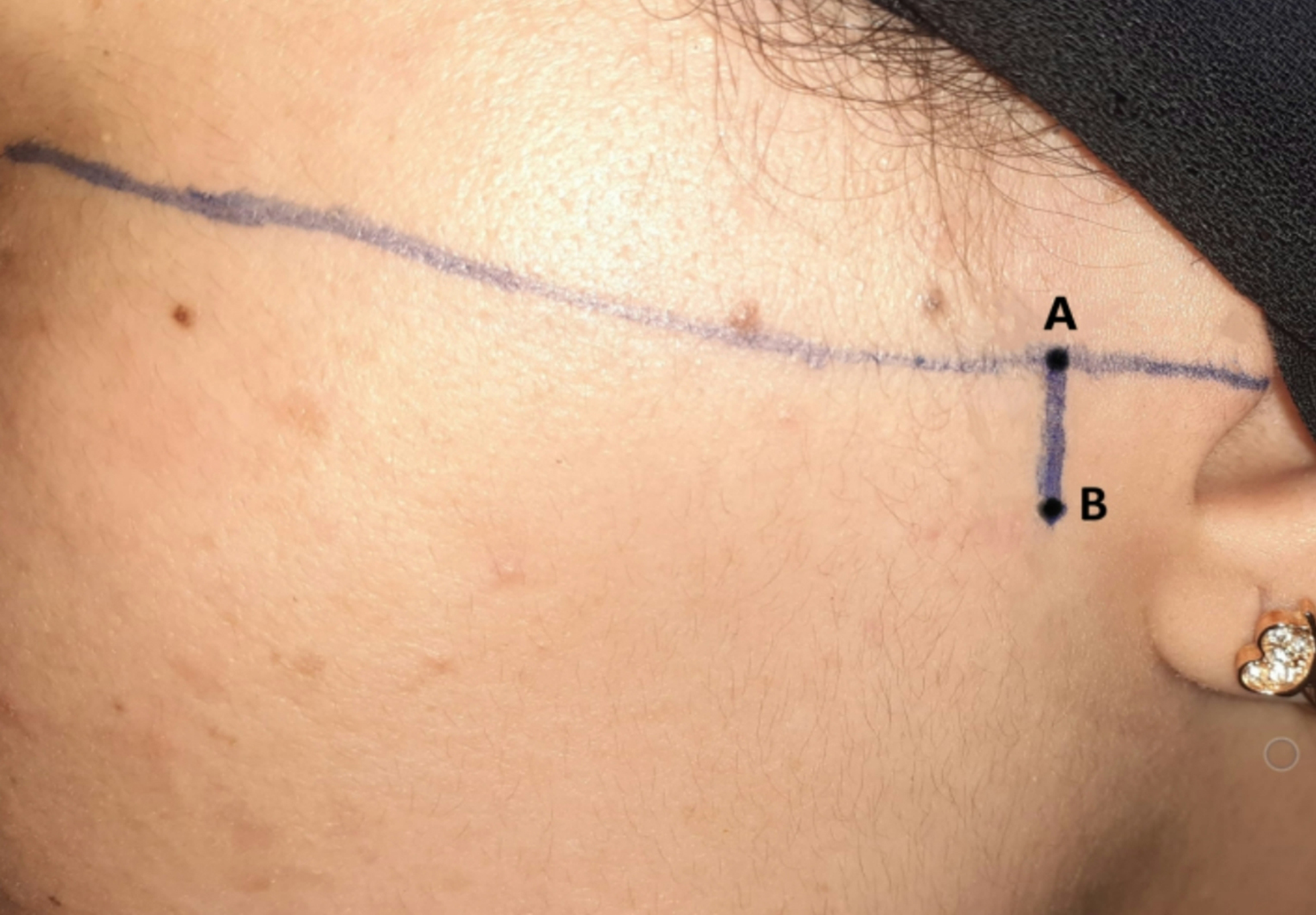
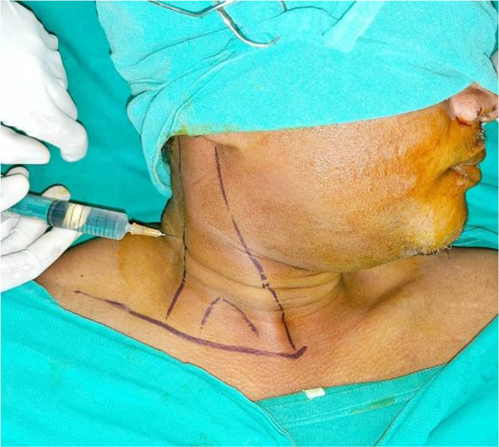
To attain the measurement of the edema scale of the patients in both groups the facial measurements had to first be recorded before surgery. With the patient seated upright and the mandible in the physiological rest position, measurements of the patient's face were taken with a measuring tape. The study employed five facial points for analysis as is shown in [Fig. 13, 14]. The most posterior point on the tragus (A), the lateral canthus of the eye (B), the most lateral point on the mouth corner (C), the soft tissue pogonium, which is the most prominent point on the chin (D), and the most inferior point on the mandibular angle (E). The measures for these three lines—A to C, B to E, and A to D—were taken three times, with an average being determined [29].
Fig. 13
Five facial points for edema analysis: The most posterior point on the tragus A, the lateral canthus of the eye (B), the most lateral point on the mouth corner C, the soft tissue pogonium, which is the most prominent point on the chin D, and the most inferior point on the mandibular angle (E) [29]
Fig. 14
A: The measures from point A (The most posterior point on the tragus) to point C (the most lateral point on the mouth corner). B: The measures from point A (The most posterior point on the tragus) to point D (, which is the most prominent point on the chin) C: The measures from point B (lateral canthus of the eye) to point E (the most inferior point on the mandibular angle)
On the third day postoperative, the patient’s same facial measurements that were taken before surgery will be repeated in the same way to record the scale of edema. The edema was calculated after subtracting the pre-operative measurement from the 3-day postoperative measurement [29].
Another evaluation for the edema was done using the edema Visual Analogue Scale where the edema ranks “None” (no inflammation), “Mild” (intraoral swelling confined to the surgical field), “Moderate” (extraoral swelling in the surgical zone), “Severe” (extraoral swelling spreading beyond the surgical zone).
4.Implant stability
Implant stability was measured using the Osstell device immediately following implant placement and 6 months postoperatively.
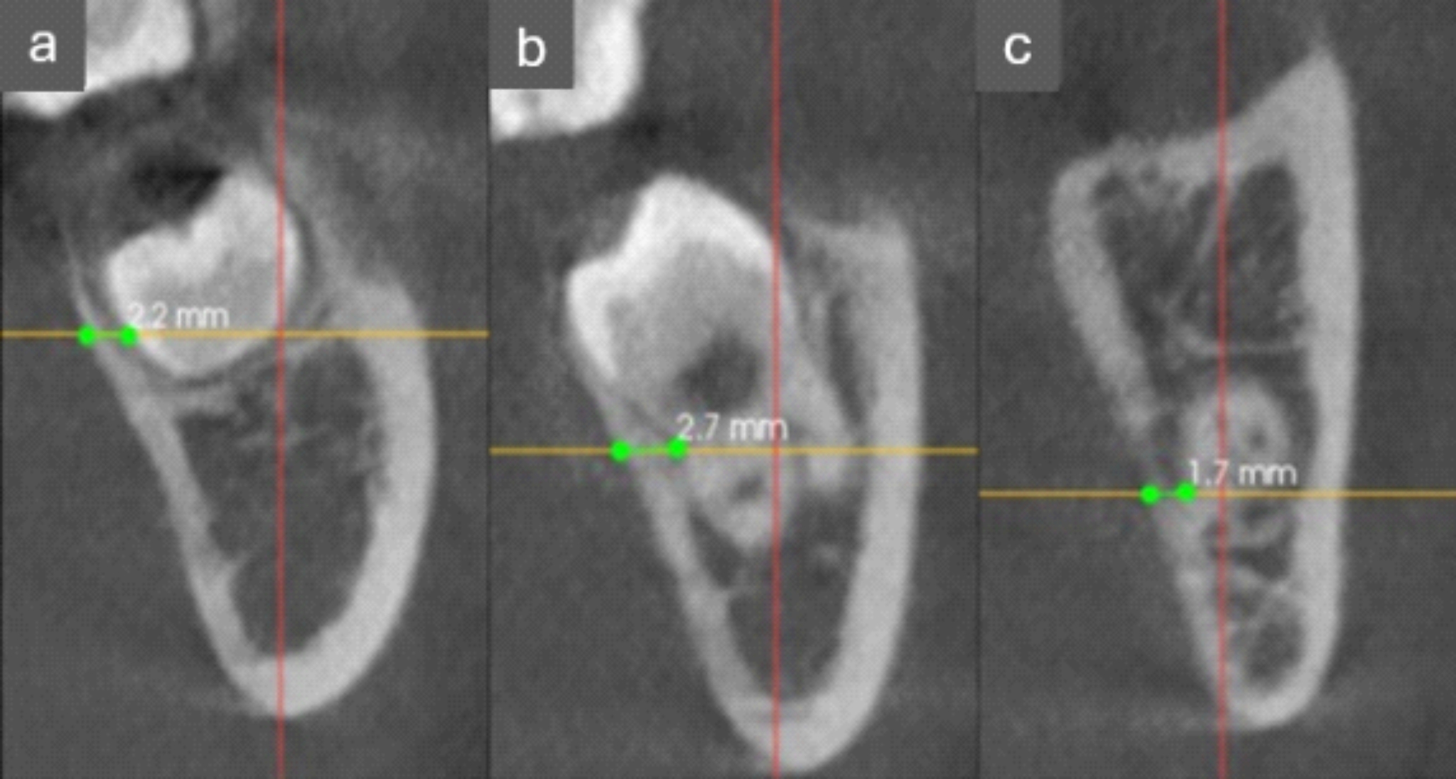
Radiographic evaluation:Automated voxel superimposition method of CBCT scans:To ensure standardization and reproducibility of the CBCT cross sectional images used in this study, superimposition of DICOM sets of each patient using Fusion module of Ondemand 3D App software was done. This 3D superimposition technique allows for sub-voxel accuracy and highly robust registration. Importing the low DICOM sets to the Fusion module of Ondemand 3D software Both files are loaded in the Fusion module at the time, first manual registration was done by approximation of the secondary scan to the primary one in axial, sagittal and coronal cuts, then automatic registration was done by the software. Cross sectional slices were obtained with the long axis of the implant in the superimposed axial, sagittal and coronal cuts, with slice thickness of 1.5 mm. these slices had the same coordination in both sets thus linear measurements could be made at the exact same sites in the primary and secondary scans simultaneously to measure the buccolingual thickness of the bone at the selected.
5.Vertical bone height gained
Using the fusion module of CBCT on the Fused Sagittal view a window showing the 6 months CBCT (in red) superimposed on the preoperative CBCT (grey) a point was made at the highest point of the bone graft using the ruler tool and extended to a point on the inferior border of the maxillary sinus, the ruler line measured must be parallel to Y-axis of CBCT as shown in [Fig. 15, 16].
Fig. 15
Method for measurement of vertical bone gain
Fig. 16
A: Fused Sagittal window. B: The preoperative window of fusion module. C: The 6 months postoperative window of fusion module
Statistical analysisNumerical data were explored for normality by checking the distribution of data and using tests of normality (Kolmogorov–Smirnov and Shapiro–Wilk tests). Age, torque, and implant stability data showed normal (parametric) distribution while edema scale, satisfaction, pain scores as well as bone changes data showed non-parametric distribution. Data were presented as mean, standard deviation (SD), median and range values. For parametric data, Student’s t-test was used to compare between mean ages in the two groups. Repeated measures ANOVA test was used to compare between the two groups as well as to study the changes by time within each group. Bonferroni’s post-hoc test was used for pair-wise comparisons when the ANOVA test is significant. For non-parametric data, the Mann–Whitney U test was used to compare between the two groups. Wilcoxon-signed rank test was used to study the changes by time within each group. Friedman’s test was used to study the changes in pain scores within each group. Dunn’s test was used for pair-wise comparisons when Friedman’s test is significant. Qualitative data were presented as frequencies and percentages. Chi-square and Fisher’s Exact tests were used to compare between the two groups regarding qualitative data. The significance level was set at P ≤ 0.05. Statistical analysis was performed with IBM SPSS Statistics for Windows, Version 23.0. Armonk, NY: IBM Corp.
Comments (0)