
Remember me
PET is a quantitative molecular imaging modality playing a crucial role in the noninvasive in vivo assessment of various diseases. In the context of clinical oncology, it is widely used in diagnosis, staging and restaging, monitoring of treatment response, and radiation treatment planning.1 Good image quality with minimum artifacts is mandatory for qualitative interpretation and quantitative analysis of PET images.2 Nonetheless, medical imaging artifacts can frequently appear in routine practice, thus compromising image quality and quantitative accuracy, in addition to the possibility of confounding interpretation and misguiding clinical decision-making.3–8 Typical artifacts that might occur in PET imaging can be classified into different categories: (i) Artifacts related to tracer distribution (eg, halo-artifact), (ii) artifacts linked to the association between PET and CT/MR images (eg, mismatch, misregistration, and motion artifacts in different regions), and (iii) artifacts that propagate from CT/MRI to PET images (eg, metals, contrast agents, and truncation artifacts).3–8 These artifacts are instigated to a large extent by quantitative image reconstruction procedures (attenuation and scatter correction) and are by no means infrequent in clinical setting. As such, there is a need for reliable techniques to capture and compensate for these artifacts.3–6 Photon attenuation and Compton scattering result in a decreased number of detected events and/or generation of pseudo signals in PET, leading to quantitatively incorrect and visually uninterpretable and misleading images. As such, attenuation and scatter correction (ASC) is crucial toward quantitative PET.7–15
Quantitatively accurate and visually interpretable PET image generation requires CT or MRI integration into scanners for ASC.7–15 In clinical setting, an unenhanced low-dose CT is commonly acquired on PET/CT scanners for ASC, even though a diagnostic CT scan with injection of contrast agent is sometimes utilized for the same purpose.7,8,11–14 Eliminating this CT scan may potentially benefit patients who require multiple follow-up PET/CT examinations, particularly the pediatric population, for which even a small decrease in the cumulative radiation dose would be valuable.11,14,16 In addition to conventional ASC algorithms implemented on PET/MRI systems and standalone PET scanners, deep learning (DL) algorithms have been recently proposed for tackling this issue.7,8,11–14,16–19 Overall, various DL-based methods have been proposed for ASC of PET images,19 such as pseudo-CT synthesis from either MRI or noncorrected PET images,20 scatter map prediction from emission data,21 and direct ASC PET image generation from non–ASC-corrected images.11
Highly intense radiopharmaceutical accumulation could result in halo or photopenic artifacts, making it challenging to interpret adjacent organs.8,18 Incorrect scatter correction results in halo artifact in PET images because negative values (which indicates prompt events as the sum of true, scatter, and random events are lower than estimated scatter events) appear nearby high-activity regions, where iterative reconstruction assigns zero to these negative voxels (nonnegativity constraint).22 In addition, halo artifacts tend to appear around high-activity regions in PET images, such as the bladder, ureters, urinary catheter, and the pyelocaliceal system of the kidneys, as urinary excretion of the radiopharmaceutical results in high target-to-background activity ratios.8,18,23 Primary tumors and local recurrences after therapy of pelvic cancers appear mostly in regions close to the bladder and metastasize along the retroperitoneal lymphatic chains up close to the kidneys.23 The appearance of halo artifacts in these regions may mask any faint abnormality that changes cancer patients' diagnosis, staging, and prognosis.23 Administration of diuretics could decrease the activity, but it increases patients' discomfort and, consequently, the risk of motion artifacts.
In clinical setting, most PET image acquisitions are performed with arms up, which reduces photon attenuation in PET and beam hardening in CT images, as well as the likelihood of body truncation.24 However, raising the arms during scanning is uncomfortable for patients, resulting in arm motion during sequential PET and CT/MRI scans. This mismatch between PET and CT/MR images, which mislocalizes events, violates PET image reconstruction assumptions and overcorrects for scatter. This violation results in striking underestimation and cold bands in transverse and coronal/sagittal plans, respectively.25 This artifact corrupts the image, which complicates PET image interpretation.24 In addition, activity outside of the body can cause the same error, which results in overcorrection of scatter.
Mismatch artifacts in PET/CT and PET/MRI can arise from motion that takes place voluntarily (bulk, head and neck, and extremities) and involuntarily (internal organs, respiration).8,11,18 These artifacts are overstated in pediatric, elderly, and claustrophobic patients.8,11,18 Some voluntary-motion artifacts could be corrected by deformable image registration between anatomical and PET images. Involuntary-motion artifacts commonly require additional hardware, such as motion-tracking devices (which is expensive and cause patient discomfort) and gated PET acquisitions (which is time-consuming and does not necessarily improve image quality). In the lung-diaphragm interface, lesions could be misregistered to the incorrect location and assigned to the wrong organ (lung lower lobes to the liver and vice versa), resulting in incorrect SUV quantification, which might impact the decision-making process.8,11,18 This misregistration between the lung and liver could be up to 4.5 cm26 and results in a curvilinear cold artifact (banana artifact).
Truncation artifacts appear owing to discrepancies in the transaxial fields of view (FOVs) between PET and CT/MRI instruments.8 This artifact occurs mostly in obese patients, patients with arms down during data acquisition, and patients referred for PET/CT or PET/MR-based treatment planning. The corresponding part of the attenuation map is missing for objects outside CT/MR images, resulting in overestimation/underestimation of SUV in the rim and inner regions, respectively.27,28 In addition, truncation of the patient body in anatomical images results in artifacts and incorrect activity quantification in PET images. Patient positioning in the center of FOV with arms up can minimize truncation artifacts.28 However, the acquisition should be with arms down for melanoma and head-neck cancer. Extended FOV CT scan, extrapolation of CT projections, dedicated MR sequences, body contour delineation on non-ASC images, joint attenuation and activity map reconstruction, and manual or semiautomatic in-painting algorithms could partially recover/mitigate truncation artifacts.25,29 However, this remains a challenging issue in overweight patients, considering that greater photon attenuation and scattering occur in obese patients, thus decreasing the quality and quantitative accuracy of images.5,30
The presence of metallic objects and prostheses, pacemakers, and oral/IV contrast agents, catheters, coiling, spine rods, and calcified lymph nodes result in photon starvation, beam hardening, and streak artifacts (because of high photon absorption) in CT and void signals in MRI.31–33 The aforementioned high-density materials do not disturb or decrease genuine PET image signals.31–33 However, they deteriorate CT image quality in dense regions and adjacent organs that propagate to PET images. Metal artifacts result in CT signal skewing, which overestimates or underestimates corresponding tissue Hounsfield units (HUs), which in turns tends to overcorrect/undercorrect PET data.31–33 In PET/CT scanners, the presence of the aforementioned highly dense objects could mimic intense radiotracer uptake overestimating the SUV by up to 20%,34 which can potentially be interpreted as an abnormality or malignant lesion, thus increasing the false-positive rate. Metallic objects and their corresponding artifacts could be easily detected on CT images. However, their effect on PET image quantification is less easily detectable. Joint attenuation and activity reconstruction and specific MR sequences were proposed to cope with metallic artifacts.35 Nonetheless, such artifacts continue to challenge PET/CT because of the wide variety of material compositions, locations, and sizes of metallic objects.31–33 Conventional metal artifact correction often exhibits suboptimal performance (significantly over/underestimating CT HUs) and might introduce new artifacts.31–33
There is a need for effective and feasible techniques to capture and compensate for such artifacts; otherwise, they can degrade PET images with time, cost, radiation dose, and patient comfort implications.8 Meanwhile, some artifacts are inevitable and cannot be corrected by repeating image acquisition.8 Furthermore, when these artifacts appear in the vicinity of lesions, the clinical relevance of suitable correction techniques increases considerably. In the clinic, a simple method to detect PET image artifacts is to visually compare ASC versus non-ASC images. However, this is cumbersome, and its use limited to cases of suspected or obvious artifacts, whereas most mild to moderate artifacts cannot be spotted at first glance. More importantly, the artifacts should not only be detected, but they also have to be corrected. The present work envisions a new paradigm in which various image artifacts are detected and disentangled from images without prior knowledge of standard of reference or ground truth. Hence, our framework is not only about quality check; the aim is to provide a very effective single-shot approach to perform quality assurance (QA; ie, including artifact disentanglement). Furthermore, the framework can be incorporated across different centers as an inexpensive tool to detect and remove image artifacts without the need for additional hardware, image reacquisition, or increase in radiation doses.
MATERIALS AND METHODSFigure 1 provides an overview of the proposed methodology adopted in the current study.
 FIGURE 1:
 Schematic of the implemented method for 18F-FDG PET image artifact detection and correction.
PET/CT Data AcquisitionIn this retrospective study, we enrolled 2087 consecutive patients referred to the Geneva University Hospital (HUG) for whole-body 18F-FDG PET/CT studies between May 2017 and September 2022 from 2 scanners. The study was approved by the institutional ethics committee of HUG (CCER ID: 2017-00922). All images were reviewed to include high-quality and artifact-free PET images for training/validation and test data sets (869 artifact-free). Images with artifacts were used for further evaluation. In addition, we included 1409 images (694 unique patients) from 8 centers for further evaluation. After cleaning the external data, 384 unique patients' images were included for further evaluation. The demographics and PET/CT image acquisition/reconstruction protocols are provided in Table 1 and Supplemental Table 1 (https://links.lww.com/CNM/A441) for HUG and 8 centers, respectively.
TABLE 1 - Patient Demographics and PET/CT Image Acquisition Parameters for HUG Data Set Train/Validation Test (Clean) Test With Artifacts Demographics Sex (female/male) 393/376 50/50 658/560 Age, y 59.5 ± 16.5 63.1 ± 18.2 62.3 ± 15.9 Effective diameter, cm 25.8 ± 2.6 24.76 ± 2.15 26.06 ± 2.76 CT acquisition Average tube current, mAS 91.7 ± 31.8 90.3 ± 26.7 92.8 ± 28.4 Pitch 0.8 0.8 0.8 kVp 80,100,120,140 80,100,120 80,100,120,140 CTDIvol 4.37 ± 3.2 4.23 ± 2.47 4.62 ± 2.9 DLP 780.1 ± 570.1 764.2 ± 439.0 830.5 ± 523.1 SSDE 3.4 ± 2.61 3.46 ± 2.15 3.56 ± 2.35 Years (background) 1.34 ± 1.18 1.31 ± 0.87 1.41 ± 1.06 PET acquisition and reconstruction parameters Time to scan, min 76.37 ± 14.21 70.36 ± 9.13 76.91 ± 13.97 Time per bed, min 2.49 ± 0.78 2.14 ± 0.48 2.53 ± 0.71 Scatter correction MBSC MBSC MBSC PET acquisition and reconstruction parameters NASC reconstruction Non-PSF, non-TOF Non-PSF, non-TOF Non-PSF, non-TOF CT-ASC reconstruction PSF + TOF 5i5s PSF + TOF 5i5s PSF + TOF 5i5s OSEM3D+ PSF + TOF2i21s OSEM3D+ PSF + TOF2i21s OSEM3D+ PSF + TOF2i21s OSEM3D PSF + TOF3i21s OSEM3D+ PSF + TOF3i21s OSEM3D+ PSF + TOF3i21s Matrix size 220 × 220 220 × 220 220 × 220 440 × 440 440 × 440 440 × 440 Slice thickness 1.5 and 2.5 1.5 and 2.5 1.5 and 2.5ASC, attenuation and scatter correction; CTDIvol, volumetric CT dose index; DLP, dose-length product; HUG, Geneva University Hospital; MBSC, model-based scatter correction; NASC, no attenuation and scatter correction; SSDE, size-specific dose estimate.
The radiation dose to patients from CT scanning was evaluated through exposure factors of volumetric CT dose index (CTDIvol) and dose-length product. The patient size was calculated by automatic extraction of body contour using an in-house developed code36 in terms of water equivalent diameter and effective patient diameter. Size-specific dose estimate was calculated as described in the AAPM report #220.37 CT acquisition parameters, including tube potential (kVp), tube current (mA), CTDIvol, patient age, sex, and size, were fed into the ImpactDose software version 2.2 (http://www.impactscan.org) to calculate the organ radiation doses and effective dose (ED) according to ICRP 10338 weighting factors.
PET-QA-NET TrainingNon-ASC PET images were input to the DL model to generate direct ASC PET images (using CT-ASC PET with PSF + TOF as reference). Additional information on image preprocessing and the network is provided in the supplemental section and Supplemental Figure 1 (https://links.lww.com/CNM/A441). The primary training process was performed as training/validation (669/100 patients) on the HUG data set. Two tests from HUG were used for further evaluation: a clean test set (100 patients) and a test with artifacts (1218 patients). Because of the high variability across the different centers, we used transfer learning with fine-tuning in the 8 different centers (20% for fine-tuning and 80% for the test set).
Evaluation Strategy Region-Wise Quantitative AnalysisVolumes of interest (VOIs)–based analysis was performed using 22 VOIs (3 cm in diameter) placed in different body regions, including 3 VOIs in the brain (right-ventricular, left-ventricular, cerebrum), 6 in the lungs (upper, middle, and lower, both right and left), 1 in the aorta, 2 in the heart (myocardium and ventricle), 3 in the liver (upper, middle, and lower parts of the liver), 1 in the spleen, 2 in the kidneys (right and left), 2 in bones (L4, L5), and 2 in muscles (right and left gluteus maximus). Different imager-derived PET metrics, including SUVpeak, SUVmean, and SUVmax, were extracted from the VOIs in the clean test set. The mean error (ME) and the mean absolute error (MAE) with respect to CT-ASC for these metrics were calculated. Bland-Altman analysis was also performed for these metrics.
Voxel-Wise Quantitative AnalysisQualitative and quantitative analyses were performed on validation and hold-out test data sets (patients without artifacts) in nonartifactual PET images. Model performance was evaluated using image level metrics, including voxel-wise ME, MAE, relative error (RE%), absolute relative error (ARE%), peak signal-to-noise ratio (PSNR), and structural similarity index (SSIM) between CT-ASC PET images, taken as standard of reference.
Qualitative Analysis of ArtifactsTwo experienced board-certified nuclear medicine physicians (I.M. and E.H. with 11 and 5 years of experience, respectively) blindly performed the qualitative analysis of 200 PET images (100 CT-ASC and 100 PET image Quality Assurance NETwork [PET-QA-NET]). Among these, 20 randomly selected cases were presented in duplicate to assess intrareader repeatability. The readers were unaware of this information. For the qualitative analysis, the physicians were asked to attribute a score on a 5-point Likert scale for each of the following: overall image quality and diagnostic confidence (1–5 [very poor, poor, average, high, and excellent]), presence of artifact (1–5 [unacceptable, mild, moderate, minor, none]), and presence and the number of lesions (1, 2, 3, 4, and ≥5). Because multiple artifacts can be present on the same scan at different regions, the analyses were performed separately for different body regions, considering the head and neck (including the brain), chest, chest/abdomen interval (diaphragm region), abdomen, pelvis, and extremities. All PET images were reviewed with their corresponding CT, per usual clinical practice using the standard clinical reading software, OSIRIX.39
Statistical AnalysisThe 2-sample Wilcoxon test was used to perform the statistical comparison of image-derived metrics between the different images (the P value was corrected using the Benjamini-Hochberg). The intraclass correlation coefficient (ICC) with 95% confidence interval was calculated to assess consistency in measurements based on a 2-way mixed-effects model for intraobserver/intraobserver variability assessment. We classified the ICC as poor (ICC < 0.40), fair (0.40 < ICC < 0.59), good (0.60 < ICC < 0.74), and excellent (0.75 < ICC < 1.00) reproducibility.40 McNemar and marginal homogeneity test were applied to provide pairwise and distribution comparisons of qualitative metrics between CT-ASC and PET-QA-NET PET images, respectively. Moreover, disagreements between readers and rates (images) were adjusted for the comparison of qualitative metrics between CT-ASC and PET-QA-NET using generalized linear models in each region.
RESULTSSupplemental Figure 2 (https://links.lww.com/CNM/A441) represents maximum intensity projections of 10 cases, including non-ASC, CT-ASC, and PET-QA-NET, from the test sets of different centers. It can be seen that the generated images are in good agreement with CT-ASC PET images.
Dosimetric EvaluationTable 1 summarizes radiation dose estimations in terms of CTDIvol, dose-length product, size-specific dose estimate, and ED calculated for 3 local sub–data sets of train/validation, test-clean, and test-artifactual. Supplementary Table 2 (https://links.lww.com/CNM/A441) summarizes the detailed dosimetric calculations for the HUG data set (train, validation, and test with and without artifacts). The average ED (mSv) to patients from CT scans were 2.91 ± 2.39 and 3.68 ± 2.79 mSv for men and women, respectively.
Quantitative Analysis on Artifact-Free Images Image-Based AnalysisThe results of the statistical analysis of image quality metrics reflecting the quantitative accuracy of the estimated tracer uptake for the test sets are presented in Supplemental Table 3 (https://links.lww.com/CNM/A441). For hold-out test sets in the HUG data set, the MAE, MSE, RE (%), ARE (%), SSIM, and PSNR were 0.09 ± 0.02, 0.03 ± 0.01, −1.19% ± 3.60%, 9.91% ± 1.53%, 0.99 ± 0.00, and 36.31 ± 1.16, respectively. For 8 different centers (80% test set), MAE, MSE, RE (%), ARE (%), SSIM, and PSNR of 0.14 ± 0.03, 0.06 ± 0.06, −1.19% ± 5.73%, 16.60% ± 2.43%, 0.93 ± 0.04, and 34.23 ± 1.39, respectively, were achieved. In addition, the voxel-wise similarity between CT-ASC and PET-QA-NET algorithms is presented as a joint histogram analysis for the test sets for each center in Supplemental Figure 3 (https://links.lww.com/CNM/A441). A correlation coefficient (R2) of more than 0.95 was achieved for all centers.
VOI-Based Analysis of Artifact-Free ImagesFigure 2 presents the Bland-Altman and bar plots for the different image-derived metrics. Supplemental Figures 4 to 6 (https://links.lww.com/CNM/A441) depict Bland-Altman plots in different regions for SUVmean, SUVmax, and SUVpeak, respectively (Supplemental Table 4 [https://links.lww.com/CNM/A441] summarizes the ME and MAE values). Mean errors of 0.0 ± 0.08, 0.0 ± 0.16, and 0.0 ± 0.12 were achieved in all regions for SUVmean, SUVmax, and SUVpeak, respectively. The statistical analysis of SUVs in all regions (except SUVmean of the aorta) showed no statistically significant difference between CT-ASC and PET-QA-NET, thus demonstrating the repeatability of quantitative metrics in PET-QA-NET as compared with CT-ASC.
 FIGURE 2:
 Top panel: Bland-Altman plots. Middle: ME. Bottom panel: MAE for the different SUV metrics in different VOIs across the 100 patients from the clean test data set. MAE, mean absolute error; ME, mean error; VOI, volume of interest.
Qualitative Analysis of Artifacted Images Intraobserver and Interobserver VariabilityIntrareader and interreader correlation coefficients (95% confidence intervals) for qualitative metrics are presented in Supplemental Table 5 (https://links.lww.com/CNM/A441). Excellent intrareader repeatability was achieved in all body regions to detect lesions. Repeatability was good for image quality and diagnostic confidence in all regions, except in the chest/abdomen interface and in the abdomen for confidence, where it was fair. None of the metrics presented poor repeatability in any body region. Considering all regions combined, good repeatability was observed for image quality, and confidence and excellent repeatability were achieved for detecting lesions and artifacts. Regarding interreader analysis, only the number of lesions in the extremities showed poor repeatability (0.28 [0.10–0.45]). All the rest of the regions and metrics showed fair, good, and excellent repeatability. Regarding all regions combined, good repeatability was observed for image quality, artifacts, lesions, and fair repeatability for artifacts.
Comparison of Image Quality MetricsComparison of qualitative metrics between CT-ASC and PET-QA-NET in terms of generalized linear model tests is summarized in Table 2 and with more details in Supplemental Tables 6 to 9 (https://links.lww.com/CNM/A441) (P values based on the McNemar, marginal homogeneity, and generalized linear model tests). In addition, Figure 3 depicts this information as a bar plot for better visualization of these metrics. For image quality (Supplemental Table 6 [https://links.lww.com/CNM/A441]), the trend was increasing the high and excellent values and decreasing poor and very poor image quality using PET-QA-NET compared with CT-ASC. The statistical test showed that these differences were significant in chest/abdomen interval because of the mismatch artifact appearing in this region. The same pattern was observed in diagnostic confidence (Supplemental Table 7 [https://links.lww.com/CNM/A441]), whereas the generalized linear model showed a statistically significant increase in image confidence using PET-QA-NET in the chest/abdomen interval, pelvis, and extremities. Moreover, considering all regions, both homogeneity and generalized linear model show a statistically significant increase in diagnostic confidence (increasing excellent and high and decreasing poor and very poor confidence compared with CT-ASC).
TABLE 2 - Statistical Comparison of Qualitative Metrics Between CT-ASC and PET-QA-NET Images Using the Generalized Linear Model (P Values) Region Quality Confidence Artifacts Lesions Head and neck 0.313 0.704 0.664 <0.05 Chest 0.623 0.698 0.098 0.219 Chest/abdomen interval <0.002 <0.05 <0.001 0.378 Abdomen 0.543 0.487 0.689 0.391 Pelvis 0.487 <0.05 0.754 0.069 Extremities 0.325 <0.05 0.106 0.398 All regions 0.411 <0.05 <0.05 0.891Statistically significant values (P value < 0.05) are highlighted in the table. CT-ASC, CT-based attenuation and scatter correction; PET-QA-NET, PET image Quality Assurance NETwork.
 FIGURE 3:
 Bar plots of image artifacts, diagnostic confidence, and image quality for different regions of the body in CT-ASC and PET-QA-NET.
The comparison of artifacts between CT-ASC and PET-QA-NET is summarized in Supplemental Table 8 (https://links.lww.com/CNM/A441). It can be seen that using PET-QA-NET decreases unacceptable and significant artifacts in all regions and provides PET images with no and minor artifacts. The artifacts are significantly removed between different regions in chest/abdomen intervals as shown by homogeneity and generalized model test. In addition, considering all regions' generalized linear models, PET-QA-NET significantly removed the artifacts (P < 0.05). The number of lesions did not show any significant difference between CT-ASC and PET-QA-NET images (Supplemental Table 9 [https://links.lww.com/CNM/A441]). However, generalized linear models that consider the effect of image type and readers show lower P values than the homogeneity test, which does not consider this information.
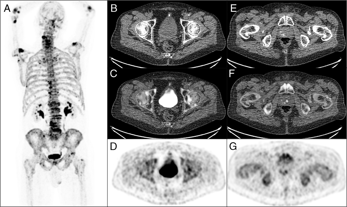
Image Analysis Halo ArtifactsAs shown in Figures 4A to C, PET-QA-NET successfully removed the halo artifacts in the pelvic region, thus improving lesion detectability, diagnostic confidence, and lesions quantification, all 3 being important for both initial diagnosis and follow-up studies, particularly in monitoring treatment response. On the other hand, the diagnostic confidence of reporting the absence of a lesion is also clinically relevant, sparing the patient unnecessary additional examinations, within the limits of the diagnostic accuracy of the modality.
 FIGURE 4:
 Axial views showing from left to right: CT, non-ASC, CT-ASC, PET-QA-NET, and the difference images of CT-ASC and PET-QA-NET. The 3 different cases demonstrate how PET-QA-NET successfully removed the halo artifact in the pelvic region, thus improving lesion detectability (A), diagnostic confidence (B), and accurate quantification (SUVmean, 3.7/2.2 in PET-QA-NET/CT-ASC) of malignant lesions (C). E–H present halo artifact case with follow-up in a patient with cervical cancer. The top row represents the pretreatment 18F-FDG-PET images with highly active areas in the cervical area (E, F). The bottom rows show images posttreatment (G, H). In the posttreatment image, diagnostic confidence was low in the pelvic region (recurrence vs responder) owing to the presence of the halo artifact. However, this artifact was removed by PET-QA-NET, and the physician was confident in this reporting.
An example of such an increase in diagnostic confidence is illustrated in Figures 4E to H, where we present a case with cervical cancer; the top rows (E and F) represent the pretreatment 18F-FDG-PET images with highly active areas in the cervical area, whereas the bottom row (G and H) shows posttreatment images. In the posttreatment image, because the pelvic bladder region is affected by halo artifacts, diagnostic confidence was low for this region (recurrence vs responder). However, this artifact disappeared on the PET-QA-NET image, hence improving the diagnostic confidence.
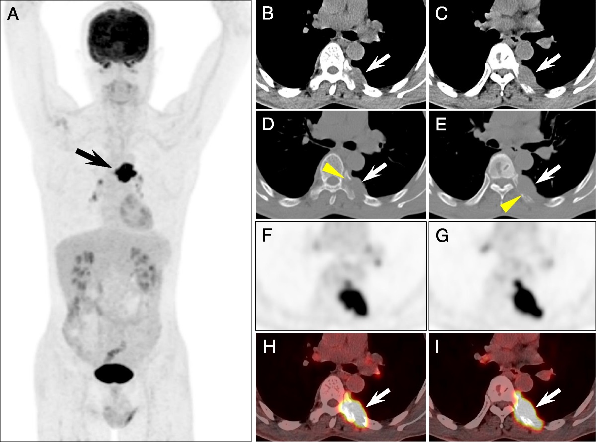
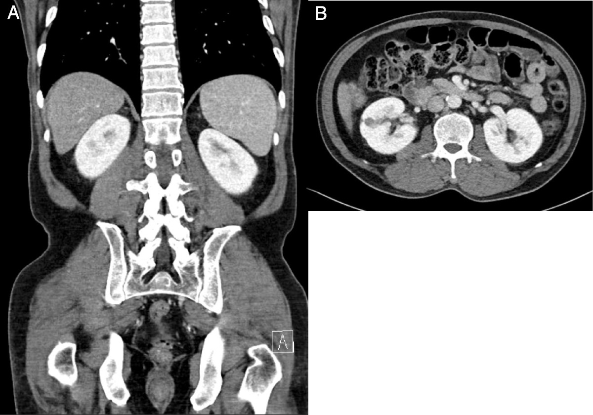
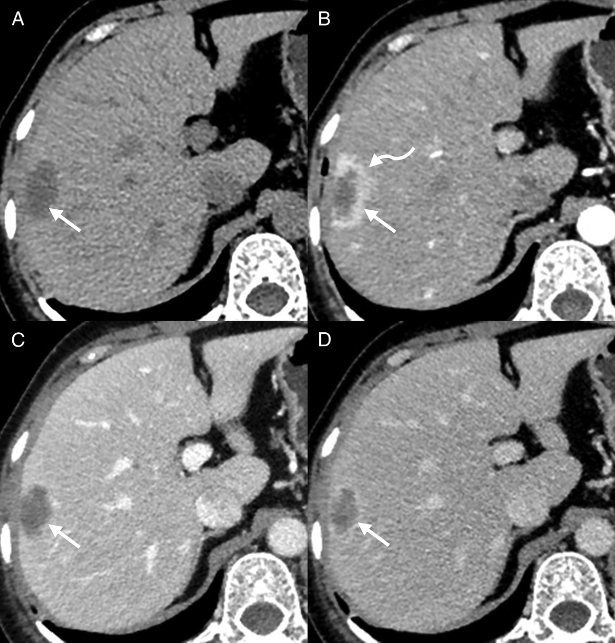
Motion Artifacts (Head, Extremities, and Respiratory)In clinical practice, respiratory motion is problematic when evaluating the diaphragmatic region. Although respiratory gating devices are widely deployed in clinical centers, their use is limited to few academic departments having access to substantial technical support. In combination with CT-ASC, non-ASC images were used to assess the presence of tracer uptake in these regions, but neither the need for the exact localization nor the need for quantification was met by this method. As shown in Figures 5A to D, PET-QA-NET images correctly pinpointed the mismatch artifact in the diaphragm regions, in terms of reduction of photopenic artifacts in the lung/liver/spleen region, quantification of SUV, and localization of lesions in supradiaphragmatic, infradiaphragmatic, or even diaphragmatic regions.
 FIGURE 5:
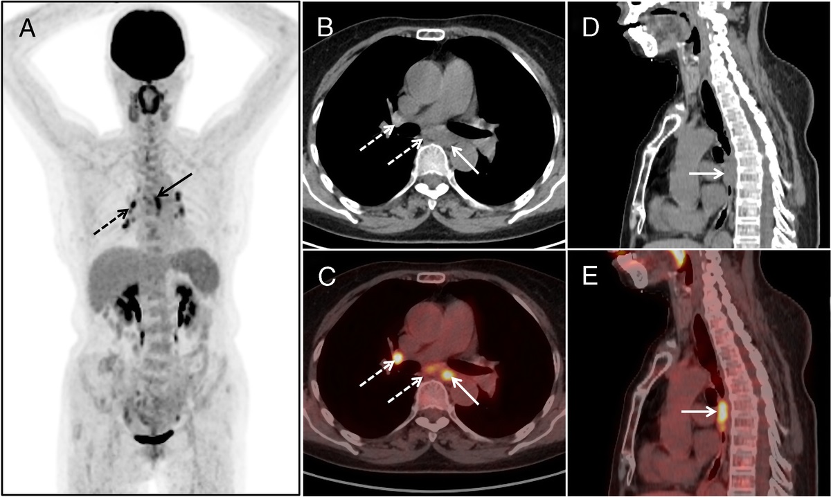
 Coronal views showing from left to right: CT, non-ASC, CT-ASC, PET-QA-NET, and the difference images of CT-ASC and PET-QA-NET. Respiratory mismatch artifacts in the chest and abdomen region where PET-QA-NET correctly removed the banana artifact in the lung/liver/spleen region (end-inhalation in CT images) in all 4 cases. In case 2 (B), although lesion detectability and lesion location did not change, the SUV values changed in these lesions. Cases 3 (C) and 4 (D) depict lesions missed on CT-ASC, which were recovered by PET-QA-NET images and correctly attributed to the liver parenchyma instead of the basis of the lung. The E and C axial views display from left to right: CT, non-ASC, fused Non-ASC, and CT, CT-ASC, PET-QA-NET, and the difference images of CT-ASC and PET-QA-NET. Head motion between CT and PET scans results in visible artifacts and quantitative bias.
Other motion artifacts, such as head motion and movement of the extremities, are very common in children and elderly patients with dementia, despite the use of appropriate constraining bands. Repeating the examination, if necessary, could be an option, but this will increase the radiation dose to the patient and negatively impact the logistics. Patient sedation could be used to avoid such problems, but this again does not come at no cost. Head motion (Figs. 5E, F) and movement of the extremities (Fig. 6) can significantly impact image quality as reflected in the CT-ASC image. It is worth emphasizing that PET-QA-NET images significantly improved the outcome. Supplemental Figure 7 (https://links.lww.com/CNM/A441) presents Bland-Altman plots for the different SUV metrics in malignant lesions affected by mismatch artifacts in the chest/abdomen interface. A summary of the statistical analysis of these metrics is presented in Supplemental Table 10 (https://links.lww.com/CNM/A441).
 FIGURE 6:
 Coronal and axial views showing from left to right: CT, non-ASC, CT-ASC, PET-QA-NET, and the difference images of CT-ASC and PET-QA-NET in 3 cases. Extremities mismatch between CT and PET images with incorrect attenuation and scatter correction of PET images, resulting in visible photopenic regions. PET-QA-NET correctly recovered the activity in these photopenic regions.
Metallic ArtifactsConcerning metallic artifacts, most commonly in the hip regions due to arthroplasties with metallic prosthetic components, visually CT-ASC images do not pinpoint the impact of metallic artifacts, as shown in Figure 7. However, quantitatively, these regions are affected by metallic artifacts. Although conventional metal-artifact reduction algorithms are commercially available, CT images are not fully recovered and are still affected by metallic artifacts, resulting in low and high HUs in different regions, which affects the resulting PET images.
 FIGURE 7:
 Coronal views showing from left to right: CT, non-ASC, CT-ASC, PET-QA-NET, and the difference images of CT-ASC and PET-QA-NET. Metal artifact case where the difference between CT-ASC and PET-QA-NET images is not perceived visually. However, quantification is affected.
Truncation ArtifactsAs demonstrated in Figure 8, the corpulence of the patient or other reasons resulting in out-of-field body parts in CT scans, mainly the arms, lead to incorrect attenuation map and corrupted CT-ASC images with truncation artifacts. In all cases, PET-QA-NET images recovered these artifacts and correctly converted them to ASC PET images without any artifacts.
 FIGURE 8:
 Coronal views showing from left to right: CT, non-ASC, CT-ASC, PET-QA-NET, and the difference images of CT-ASC and PET-QA-NET. Truncation artifact cases where a corpulent patient whose arms are out of the CT scan field of view, resulting in an incorrect attenuation map and corrupted CT-ASC images (A and B). In C, a case referred for radiotherapy treatment planning, where a fixator was used for the left arm resulting in out-of-field right arm in the CT scan, which caused truncation artifacts and corrupted images in CT-ASC. PET-QA-NET images reduced these artifacts.
DISCUSSIONArtifact-free 18F-FDG PET images were used for the development of PET-QA-NET framework. PET-QA-NET performance was evaluated for different 18F-FDG PET image artifacts toward fast and precise routine QA in the clinic. We demonstrated that PET-QA-NET could readily pinpoint several artifacts and disentangle these artifacts, including mismatches and motion, truncation, metal, and halo artifacts in 18F-FDG PET images. The qualitative assessment performed by 2 experienced readers revealed that the number of lesions detected did not change significantly between PET-QA-NET and CT-ASC 18F-FDG PET images, except lesions located in the head and neck region, where the detection of unifocal abnormalities increased with PET-QA-NET. Nevertheless, there was a clear improvement in image quality with the correction of significant artifacts, resulting in an increase in diagnostic confidence, particularly in the diaphragmatic regions, the pelvis, and the extremities. In other words, the regions are affected mainly by artifacts in whole-body 18F-FDG PET images in everyday clinical practice.
Promising results have been reported with different DL-based ASC methodologies.8,11,14,16,18,41
Comments (0)