
Remember me
Refractive index is a fundamental parameter for identifying the composition of a substance. Hence, developing a sensor capable of accurately and reliably measuring RI is of great importance. This study proposes a D-shaped photonic crystal fiber sensor for enhanced surface plasmon resonance (SPR) sensing. The structure incorporates dual-sized air holes (D₁ and D₂) within a silica core to optimize light confinement, mode coupling, and propagation characteristics. One side of the fiber is polished to form a D-shaped profile, exposing the inner air holes and allowing direct interaction between the guided light and a thin gold layer, which supports efficient SPR excitation. The sensor is capable of detecting RI variations in the range of 1.28–1.44. It achieves an average wavelength sensitivity of 3875 nm RIU−1, highlighting its effectiveness in monitoring ambient RI changes. The results confirm the sensor’s suitability for a wide range of applications, including biochemical analysis, environmental monitoring, and medical diagnostics.
Export citation and abstractBibTeXRIS
In recent years, surface plasmon resonance (SPR)-based sensors have attracted significant attention due to their simple light input, controlled propagation, wide sensing range, and high precision and sensitivity [1, 2]. SPR sensors based on dielectric structures, including multilayer stacks [3], planar waveguides [4], and photonic crystals [5], provide benefits such as simpler fabrication and easier integration with lab-on-chip platforms. In comparison, the proposed D-shaped photonic crystal fiber (PCF) sensor offers longer light–analyte interaction lengths and remote sensing capabilities, enhancing sensitivity for practical applications. These advancements align with the growing use of optical fiber-based sensing in diverse areas, including biochemical detection, bio-imaging, medical diagnostics, and environmental monitoring [6]. Specifically, PCF based SPR technology has been identified as a very efficient and reliable method for optical sensing applications in recent times [7, 8]. Conventional optical fiber SPR sensors tend to be beset by limitations such as complicated operations and unwanted mode coupling, which can be mitigated perfectly by combining PCF with SPR technology [9]. This blended method benefits with many things such as high sensitivity, immunity to electromagnetic interference [10], flexible and compact nature, as well as successful applications in non-linear optics, supercontinuum generation, and sensing systems [11, 12]. Tunable structural geometry, control of birefringence, and the optical parameter design flexibility of PCF also render it suitable for a range of sensing applications [13]. Studies show that large mode field diameter fibers enhance light-analyte interaction, leading to increased sensitivity. The D-shaped PCF, in which the core is exposed by polishing a side of the cladding, has been observed to exhibit significant improvements in RI sensitivity. Present work aims at maximizing the structural parameters of these fibers, specifically the metal layer and fiber core, to enhance sensing performance [14].
Ayyanar et al proposed a dual-core PCF sensor for cancer detection using a selective infiltration technique. The central air hole is removed to form the primary silica core, and a small hollow cavity of 0.6 μm beside it is used to introduce biological samples, enabling effective interaction with the guided light for analysis [15]. Vigneswaran et al designed a PCF to measure salt concentration in seawater, where the seawater-filled cladding hole acts as the analyte core. In the dual-core design, the central hole is removed to form the silica core, and another core is created by injecting the sample into a middle cavity above the horizontal row. The RI of seawater varies from 1.3326 to 1.3505 as salinity changes from 0% to 100% at room temperature [16]. Enhancing the sensor’s performance involves incorporating the SPR technique into the PCF structure. This requires coating the fiber surface with a conductive material, where light interacts resonantly with the free electrons on the metal. At resonance, significant energy is absorbed, producing detectable optical losses [17]. Hasan et al [18] proposed a gold-coated PCF structure with a double-layer air hole distribution and omitted holes to generate a birefringent effect. With a 40 nm thickness of the gold layer, this sensor showed a peak sensitivity of 2200 nm RIU−1 in the range of refractive index from 1.33 to 1.36. Nevertheless, injecting or coating metal into the inner holes was a practical challenge in the fabrication process. Kiroriwal et al introduced a PCF-based hemoglobin sensor in which a gold plasmonic layer is coated along the inner wall of the fiber. The sensor adopts an external sensing scheme to overcome the drawbacks of conventional internal sensing arrangements and demonstrates reliable performance within the RI range of 1.37–1.39 [19]. However, applying a metal coating inside the fiber presents significant fabrication challenges, which has encouraged researchers to adopt more practical approaches such as placing the plasmonic layer on the polished plane of D shaped PCFs. Gold is widely considered the optimal plasmonic material due to its chemical stability, resistance to oxidation, strong optical response, and minimal interband transition losses [20, 21]. Kaur and Kumar [22] introduced a sensor model capable of detecting a range of biological substances such as plasma (1.34), white blood cells (1.36), water (1.33), hemoglobin (1.38), and even harmful substances like methanol (1.314), cancer tissues, and intestinal mucosa (1.338–1.382).
Recent advancements in PCF based SPR sensors have focused on enhancing sensitivity while simplifying fabrication. Chao et al introduced a compact SPR-PCF design with only four circular air holes, achieving 11 000 nm RIU−1 sensitivity with minimal structural complexity [23]. Expanding upon this concept, Chao et al incorporated elliptical air holes and an external gold coating to enhance birefringence, resulting in a significantly higher sensitivity of 116 500 nm RIU−1 [24]. Extending the concept to temperature sensing, Chao et al developed a trapezoidal-shaped SPR-PCF with Ag/SiO₂ coating, achieving a thermal sensitivity of 5200 pm/°C [25]. Plasmonic sensor research has increasingly focused on multi-mode resonant structures to improve sensitivity across diverse applications. Chao et al developed a metal-shell nanorod-based plasmonic metamaterial absorber capable of multi-channel sensing in the visible range, achieving sensitivities up to 600 nm RIU−1 and temperature sensitivity of 0.22 nm/°C [26]. Tan et al proposed a pentagonal-ring-shaped Fano resonance sensor with an oblique path, yielding high RI and alcohol concentration sensitivities of 6560 nm RIU−1 and 236.25 nm Ca−1, respectively [27]. Chao et al introduced a compact MIM-based plasmonic pressure sensor that demonstrated ultrahigh pressure sensitivity of 592.44 nm MPa−1 [28]. These works demonstrate that resonator geometry and field confinement techniques play a critical role in advancing high-performance nanophotonic sensors.
Advancing sensor performance has motivated researchers to explore microchannel-based PCF configurations. Guo et al reported a U-shaped PCF-SPR sensor employing Au–TiO2 coatings for accurate analyte RI detection. Introducing elliptical air holes near the fiber core disrupts the structural symmetry of the PCF, producing strong birefringence and enhancing sensing capability within the RI range of 1.36–1.43 [29]. Chen et al proposed a double D-shaped PCF-SPR sensor capable of independently measuring RI and temperature, where a gold film is deposited on the two large semicircular grooves and the adjacent air hole. The design operates effectively within an RI range of 1.30–1.42, offering stable performance for multi-parameter sensing applications [30]. Mehedi et al proposed a PCF biosensor featuring an innovative H-shaped architecture tailored for distinguishing healthy cells from cancerous ones. The design incorporates an exposed suspended core supported by four SiO2 channels, which significantly impact the confinement loss behavior of the sensor. Gold is applied as the plasmonic coating along the fiber walls, with a TiO2 adhesive layer added to further enhance stability and sensing performance [31]. Bingjie Zha et al developed a stretchable elastomer optical fiber sensor integrated into a wearable belt for simultaneous respiratory and heart rate monitoring. The optimized design showed stable performance across different body positions, including ballistocardiography detection in the lying position. It achieved high accuracy with maximum errors of 1 bpm for respiration and 3 bpm for heart rate, closely matching manual and ECG measurements [32].
This research introduces the structure of a D-shaped PCF with dual-diameter air holes in the core and a gold coating over the U-shaped polished surface. A comprehensive investigation was performed through varying the diameters and thickness of the gold layer to determine the best structure for sensing purposes. The spectrum of confinement loss was used to find the resonance wavelength for different refractive indices, and the sensitivity obtained was extensively studied. The designed structure achieved a high average sensitivity of 3875 nm RIU−1, indicating its strong sensing capability. The U-shaped gold-coated microchannel brings the plasmonic layer closer to the fiber core while simultaneously acting as a confined sensing region that holds the analyte near the core, thereby enhancing mode coupling and improving detection efficiency. Additionally, the optimized air hole arrangement enhances evanescent field interaction at the sensing interface while maintaining strong light confinement, making the proposed sensor highly suitable for accurate and efficient biosensing applications.
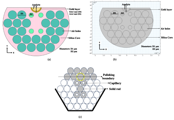
The work suggested in this research presents a structure that has a silica core with double-sized air holes, marked as diameters D1 and D2, with a coating of gold and an analyte layer deposited over the gold surface. The diameter D3, measuring 5.92 µm, corresponds to the outer radius of the third air hole and is used to determine the thickness of the gold layer. The structure is drawn from a D-shaped PCF that has been incorporated with SPR sensing technology for improving light-analyte interaction through parameters and fiber geometry optimization. The periodic arrangement of air holes offers efficient light confinement and propels the manipulation of propagation characteristics. TM mode is considered in this design because SPR excitation occurs only when the electric field has a component perpendicular to the metal surface, which is a characteristic of TM polarization. Unlike traditional D-shaped PCF sensors, the proposed structure shown in figure 1(a) features a gold layer deposited along the curved top end of the fiber in a U-shaped microchannel. The U-shaped channel employs the negative-curvature principle and supports the Dirac mode with a power-law field distribution, enabling strong field localization and efficient plasmonic coupling. Owing to its near-zero dispersion at the Dirac point, the resulting slow-light behavior further enhances light–matter interaction, thereby improving sensing performance [33]. By wrapping the plasmonic layer around the fiber, the U-shaped geometry reduces the core-to-metal distance, enhancing the interaction between the core and surface-plasmon modes and improving coupling efficiency [34]. Moreover, it facilitates easier analyte infiltration and more uniform interaction with the metal surface, resulting in higher sensitivity compared to a flat D-shaped interface [35]. The design enhances the surface area, which enables easier interaction between the guided light and the analyte, which takes place above the region coated with gold. There is also a short linear portion of the gold coating that is stripped off, and it is filled with analyte. The analyte serves as an essential sensing interface, facilitating the detection based on refractive index via the SPR effect.
Figure 1. (a): The 2D-structure of fiber with materials used for fabrication (b): cross-sectional view of the proposed design of the D-shaped PCF (c): stack preform of the proposed design of the D-shaped PCF.
Download figure:
Standard image High-resolution imageThe idea of using dual-sized air holes and a gold-coated surface is based on observations that larger diameter air holes ensure the confinement of light inside the fiber core, whereas smaller diameter air holes enable light waves to penetrate and reach the metal–analyte interface, leading to the excitation of more free electrons. The dual-sized air hole structure aids in producing an evanescent field more effectively. Both gold and silver are considered the most suitable plasmonic materials for achieving SPR. However, although silver films can be more economically feasible to fabricate, gold films are widely preferred due to their lower susceptibility to oxidation and superior chemical stability [36].
Figure 1(b) illustrates the cross-section of the proposed fiber structure with two distinct air hole diameters (D₁ and D₂), the structural shape, the gold-coated surface, and the areas meant for analyte insertion. The structure consists of a one-side polished silica core, 23 big air holes of diameter D₁, and 4 small air holes of diameter D₂. Figure 1(c) illustrates the stack preform of the proposed PCF structure, which is fabricated using the stack-and-draw technique by precisely arranging capillaries and rods and drawing them into fiber under controlled conditions.
The proposed sensor structure can be fabricated using the widely adopted stack-and-draw method. In this process, a combination of capillaries and solid rods is carefully assembled into a preform and then drawn into fiber at a controlled temperature and speed [37]. The D-shaped structure of the PCF is obtained by selectively polishing one side of the circular fiber using side-polishing or wheel-polishing methods. The subsequent U-shaped microchannel can be created through V-groove edge-polishing or ion-beam milling, which allows controlled removal of material along the polished surface [29, 38, 39]. The plasmonic layers can be deposited using electron beam evaporation, a type of physical vapor deposition. This method ensures a high-purity metal coating and allows precise control of the layer thickness, which is important for consistent sensor performance [40]. Finally, the analyte can be introduced into the sensing regions through an appropriate infiltration process [41], and pressure-assisted filling is applied to ensure complete filling, followed by immediate sealing of the fiber to prevent leakage and maintain sensor stability.
To characterize the complex RI of fused silica, the Sellmeier equation is used, as represented in equation (1) and defined in [42]:
Here, n denotes the RI of silica. The constants B₁, B₂, B₃, C₁, C₂, and C₃ used in the Sellmeier equation are taken from, with values: B₁ = 0.696 163 00, B₂ = 0.407 994 26, B₃ = 0.897 479 40, C₁ = 0.004 679 148 26, C₂ = 0.013 512 0631, and C₃ = 97.934 0025, as reported in [21].
The dielectric behavior of gold (Au) is described by the Drude–Lorentz model, as given by equation (2) and elaborated on [21] as:
where  Au represents gold’s permittivity, at high frequency the permittivity is denoted by ∞, plasma frequency is ωD, angular frequency is ω and decaying frequency is γD. The values for these above-mentioned parameters are ∞ = 5.9673, ω = 2πc/λ and c is the velocity of light in vacuum, ωD/2π = 2113.6 THz, γD/2π = 15.92 THz and weighting factor Δ = 1.09. Finally, the spectral width of Lorentz ГL/2π = 104.86 THz and oscillator strength is ΩL/2π = 650.07 THz.
Numerical analysis is carried out using the finite element method (FEM) in COMSOL Multiphysics. FEM is a numerical technique that solves complex structures by dividing them into smaller, simpler parts. For obtain precise results, a physics-controlled mesh model has been utilized to mesh the sensor’s structure with extremely fine element sizes. The computational domain is discretized using a mesh consisting of 21 051 triangular elements and 1519 edge elements. The mesh parameters include a maximum element size of 1.12 µm, a minimum element size of 0.002 µm, a maximum element growth rate of 1.25, and a total mesh area of 704.5 µm2. This meshing strategy was applied uniformly across the entire structure. The final mesh configuration was determined through a systematic mesh refinement analysis, which confirmed that further increases in mesh density yielded no appreciable variation in the calculated effective index or confinement loss. Thus, the selected mesh was considered sufficiently refined to ensure stable, accurate, and converged simulation results for the proposed sensor. Finally, scattering boundary conditions were applied to the outermost layer of the PCF to effectively suppress any scattering-related losses.
The proposed design is analyzed for its sensing performance over the wavelength range of 1.10–3.25 μm using COMSOL Multiphysics. The structure is planned with a PCF diameter of 32 μm and pitch (distance between the centers of two consecutive air holes) of P is 4.8 μm. Starting values for diameters of air holes are assigned as D1 is 4.042 μm and D2 is 2.742 μm, and light propagation properties are studied across a wavelength span of 1.10–2.0 μm.
3.1. Air-hole’s diameter optimizationIn order to complete the diameters of the two air holes, birefringence values were studied. Effective mode index data for the structure were exported at different wavelengths, and the values of both x-polarized and y-polarized light were noted. Using the data and applying equation (3), the birefringence value was calculated [43, 44],

where, neffX is the real part of effective mode index of x-polarized light and neffY is the real part of effective mode index of y-polarized light.
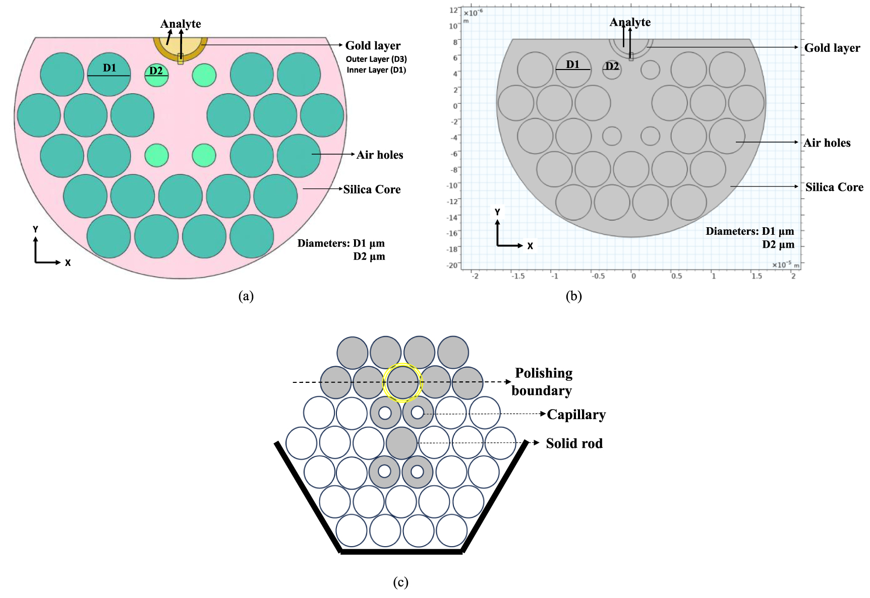
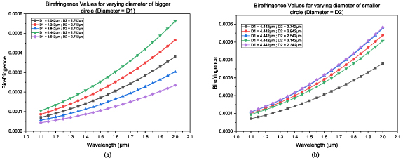
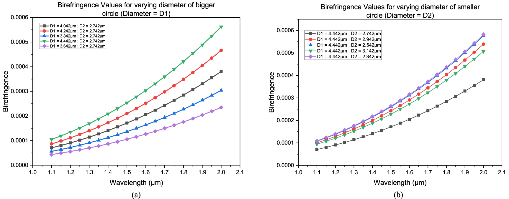
The diameters were changed, and birefringence for each combination was observed. Figures 2(a) and (b) show a comparison of birefringence with different diameters. In figure 2(a), the diameter D1 was changed within the range of 3.642–4.442 μm, while the diameter D2 remained fixed at 2.742 μm. Upon fixing the diameter D1 at 4.442 μm, figure 2(b) shows the birefringence values for varying diameter D2 in the range of 2.342–3.142 μm, with the highest birefringence value of 0.000 582 268 observed when λ is 2.0 μm for D2 is 2.342 μm. Maximization of birefringence enables more efficient filtering of unwanted polarization components, and hence improved sensor performance. Greater birefringence allows clearer separation of the X and Y polarization modes, enabling precise tuning of the resonance conditions for detecting small refractive index changes. The order and number of air holes in the PCF define the structural asymmetry that governs birefringence, and a larger birefringence difference strengthens the sensor’s ability to achieve single-window detection, minimize polarization-dependent losses, and sense even finer refractive index variations with improved accuracy [45]. Upon analysis, the values of greater air hole diameter and lesser air hole diameter were determined as D1 is 4.442 μm and D2 is 2.342 μm.
Figure 2. (a): Birefringence value comparison for varying diameter D1 (b): birefringence value comparison for varying diameter D2.
Download figure:
Standard image High-resolution image 3.2. Gold-layer thickness optimizationA PCF-based SPR sensor operates through the interaction between the core-guided mode and the plasmonic mode, occurring when light of a specific wavelength excites the metal surface. This interaction produces a leaky mode, facilitating energy transfer from the core to the plasmonic layer. The process is dictated by the phase-matching condition, with the wavelength at which coupling is strongest known as the resonance wavelength. When an analyte is present near the metal surface, it modifies the local RI, which changes the effective refractive index (neff). This alteration disturbs the phase-matching condition, causing a shift in the resonance wavelength and marking the point of maximum energy transfer [46].
The thickness of the gold layer (tAu) was also optimized to provide a peak confinement loss at the resonance wavelength, where light interacts with the free electrons at the surface of the gold layer. In order to examine the confinement loss, gold films of different thicknesses were deposited, and the loss behavior of the fiber was measured under resonant conditions. The confinement loss is defined by the equation (4) [47]:
where λ denotes the wavelength of light in μm, Im(neff) is the imaginary part of the effective refractive index, and L represents the confinement loss measured in dB cm−1.
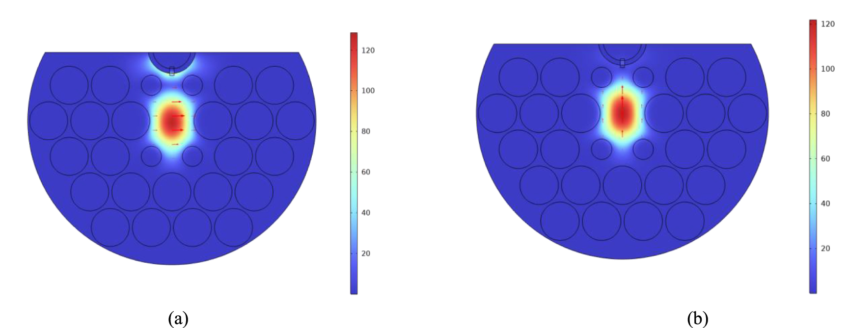
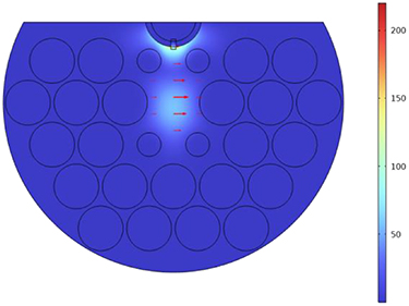
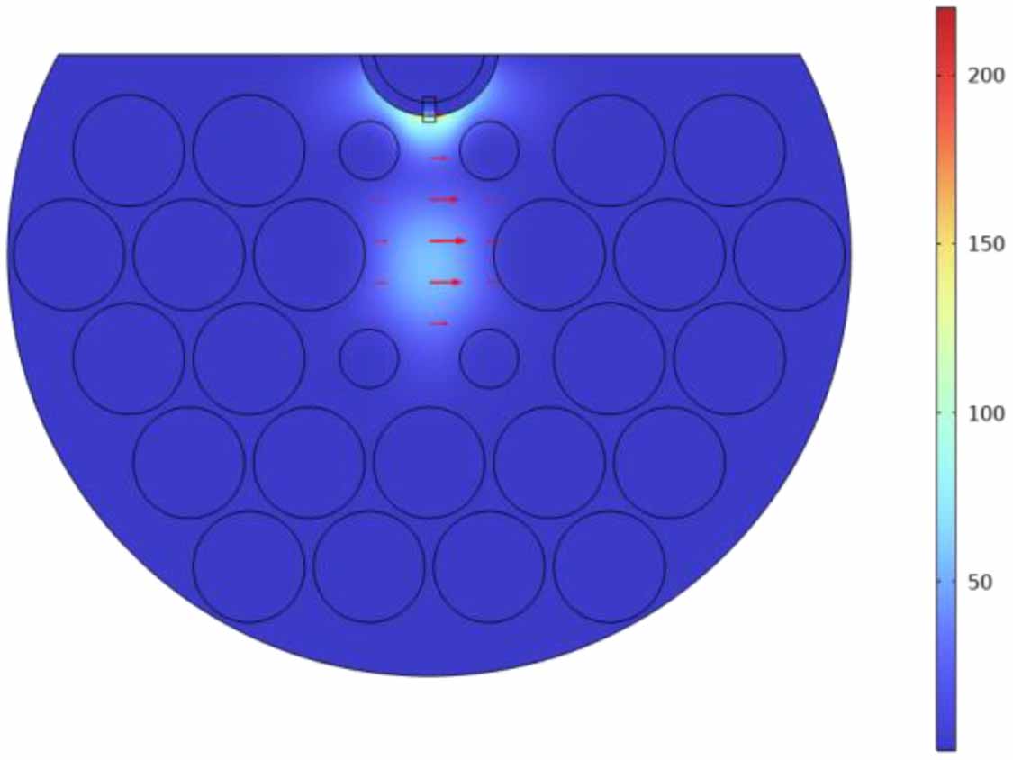
Figures 3(a) and (b) demonstrate the coupling between x-polarized and y-polarized light as it travels through the fiber. Even without SPR, there is a weak interaction between the guided light and the gold-coated surface. This phenomenon indicates the first coupling between the core mode and the free electrons on the metal surface. When gold SPR conditions are achieved, coupling is enhanced, leading to an extensive enhancement of confinement loss. Confinement loss is most pronounced whenever the propagated light fully resonates with the gold surface electrons, suggesting maximum mode coupling. The SPR condition for the light traveling through the PCF is shown in figure 4.
Figure 3. (a) x-polarized light propagation and interaction of light with metal surface; (b) y-polarized light propagation and interaction of light with surface.
Download figure:
Standard image High-resolution imageFigure 4. Coupled mode, representing highest confinement loss.
Download figure:
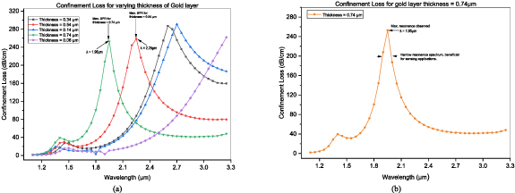
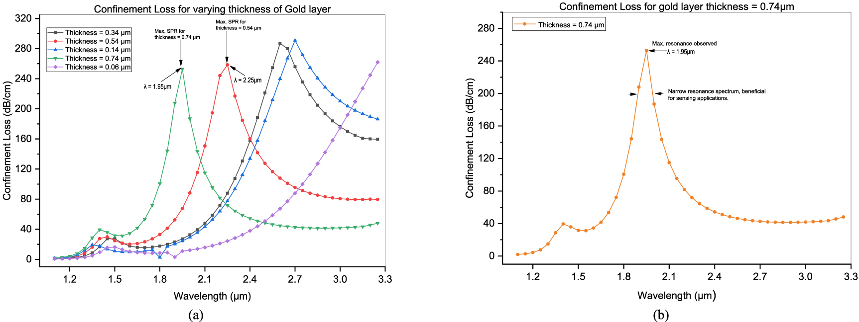
Standard image High-resolution imageTo maximize the sensing performance, the influence of the varying thickness of gold layer (tAu) over the range 0.06–0.74 μm was studied. It was reported that with the gold layer thickness is 0.74 μm, peak confinement loss of 253 dB cm−1 at the resonant wavelength λ is 1.95 μm was attained. This particular thickness was chosen for examination because it is capable of creating a sharp peak loss within a small spectral band, a desirable property for achieving improved sensing efficiency. Figure 5(a) shows the variation of the confinement loss with various thicknesses of the gold layer. With an increase in thickness from 0.06 μm to 0.74 μm, the resonance peak is shifted toward lower wavelengths along with the reduction in the bandwidth of the resonance. Figure 5(b) demonstrates the confinement loss profile for optimized thickness of the gold layer at ‘tAu’ equals to 0.74 μm at a wavelength between 1.10 μm and 3.25 μm. At resonance wavelength when λ is 1.95 μm, a high value of confinement loss with a steep peak of 253 dB cm−1 is seen. It shows the resonance bandwidth of the narrow linewidth. This behavior dramatically enhances the sensor’s sensitivity and selectivity and renders it well suited for efficient sensing applications.
Figure 5. (a): Different trends of loss at resonance condition for same structure with varying thickness of gold layer. (b): confinement loss curve for chosen thickness of gold layer having high peak and narrow spectrum of bandwidth.
Download figure:
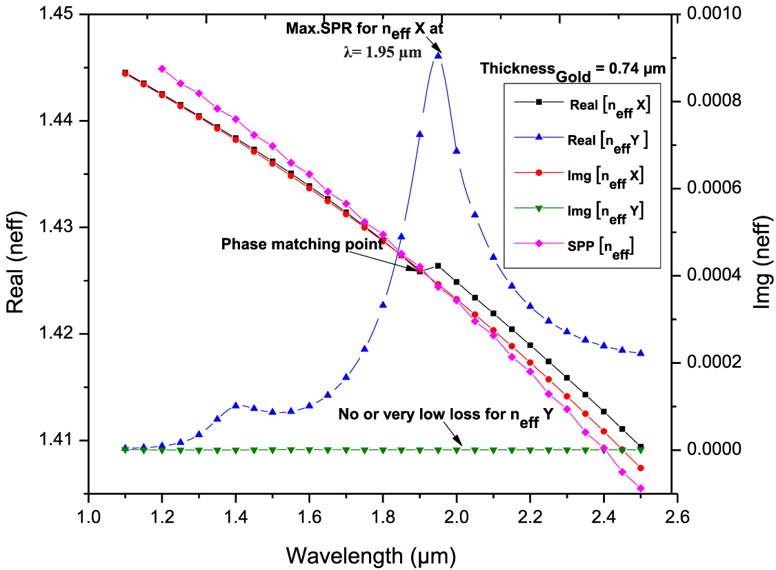
Standard image High-resolution imageFigure 6 shows dispersion relation between the imaginary and real parts of the neff over the wavelength range of 1.10–2.5 μm. As the wavelength increases, the real part of neff for both the core-guided mode and the SPP mode gradually decreases. For x-polarized light, these two indices move closer and eventually intersect around 1.95 µm. At this point of intersection, the imaginary part of the core mode reaches its maximum value, indicating that the core and SPP modes satisfy the phase-matching condition. This confirms the occurrence of strong coupling between the modes, and the corresponding wavelength is identified as the resonance wavelength. Conversely, the y-polarized mode shows negligible interaction with the plasmonic interface, and no resonance behavior is observed within this spectral range.
Figure 6. Dispersion relations of the core-guided mode as a function of wavelength.
Download figure:
Standard image High-resolution imagePerformance of the sensor was tuned by varying important parameters, such as gold layer thickness and air hole diameters. Effect of each parameter was investigated one at a time while other structural parameters were kept constant. During the whole optimization process, a refractive index of 1.00, which corresponds to air, was used as the simulated analyte.
3.3. Sensing capability analysisThe diameters of the air holes, D1 and D2, play a crucial role in guiding light within the core. Variations in their dimensions significantly influence the birefringence, as illustrated in figures 2(a) and (b). Moreover, the thickness of the gold layer, tAu, deposited on the curvature of the structure contributes a lot towards the confinement loss and resonance properties, as seen in figures 5(a) and (b). After thorough examination, the final values for the diameters were determined to be, D1 is 4.442 μm and D2 is 2.342 μm, and the thickness of the gold layer was determined to be, tAu is 0.74 μm. With all structural parameters determined, the subsequent step is introducing analyte samples with different refractive indices to determine the sensitivity of the fiber design. The wavelength sensitivity is calculated using the following expression, equation (5) [48]:
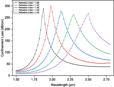
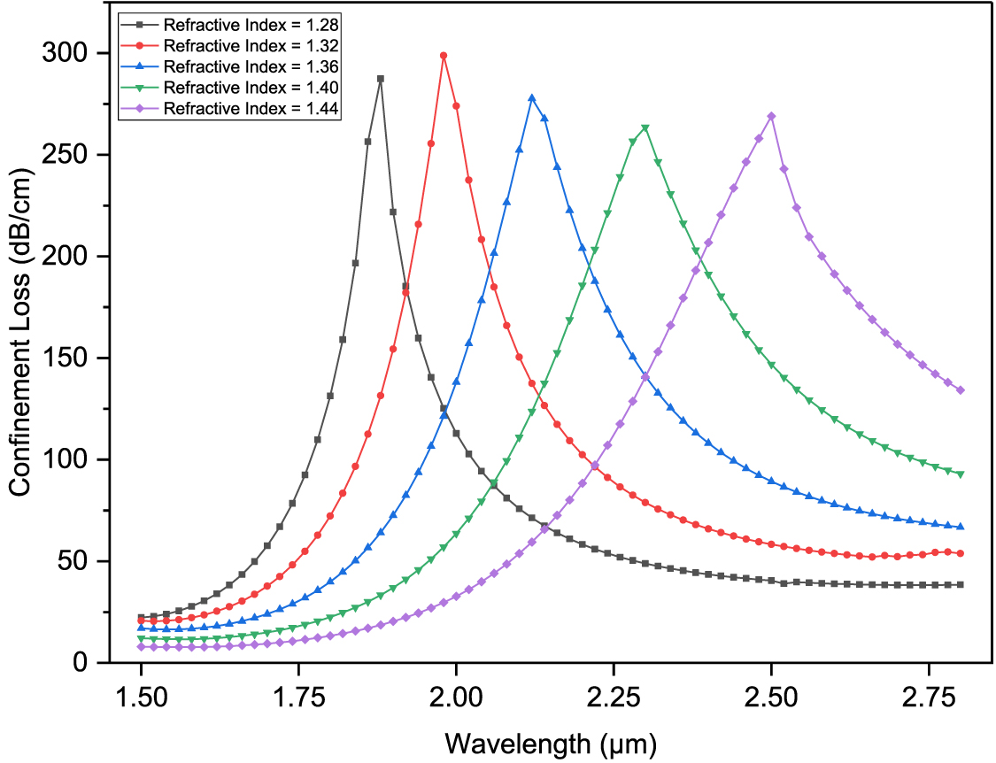
The dependence of confinement loss on the RI of the analyte was investigated in this study. Figure 7 illustrates the confinement loss versus wavelength for different RIs used as analyte samples, ranging from 1.28 to 1.44. The measurement was taken for a wavelength range of 1.50–2.85 μm. The resulting curve illustrates a shift of the peak confinement loss toward longer resonance wavelengths as the sample’s refractive index increases, indicating that SPR occurs at higher wavelengths with higher surrounding RI. This red-shift and the increased sensitivity arise from enhanced phase-matching between the core-guided mode and the surface plasmon mode, which improves field confinement at the metal–analyte interface and strengthens light–matter interaction.
Figure 7. Variation in the peak loss with varying refractive index of the analyte sample.
Download figure:
Standard image High-resolution imageFor the specified RI range, a difference in wavelength of 0.62 μm was noted, where the longest wavelength is when λ is 2.5 μm for RI equal to 1.44 and the shortest, λ is 1.88 μm for RI equal to 1.28. The maximum confinement loss of 298.83 dB cm−1 was noted when λ is 1.98 μm for RI equal to 1.32, while the minimum confinement loss of 263.54 dB cm−1 was noted when λ is 2.30 μm for RI equal to 1.40. This means that in the RI range of 1.28–1.44, the variation in confinement loss was at most 35.29 dB cm−1 over the wavelength range of 1.50–2.85 μm.
This change provides valuable information about differences in the RI of the sample. Any sample anomaly will alter the sample RI, resulting in slight deviations from the nominal value. These differences can be detected by plotting the confinement loss versus wavelength and comparing it with that of a known RI reference sample.
To determine the sensitivity, the wavelength sensitivity was calculated using its standard expression, as it is less affected by noise compared to amplitude sensitivity. After computing the wavelength sensitivity by determining the change in resonance wavelength with respect to RI shift, the sensitivity was 2500 nm RIU−1 for the RI range of 1.28–1.32. From 1.32 to 1.36, sensitivity rose to 3500 nm RIU−1, and from 1.36 to 1.40, it again rose to 4500 nm RIU−1. For the last sample range of 1.40–1.44, sensitivity was recorded as 5000 nm RIU−1.
The practical relevance of the selected RI range is evident from the analytes listed in table 1, which includes a range of biological and chemical substances with refractive indices between 1.28 and 1.44. These encompass physiological fluids, cancerous and parasitic cells, bacterial pathogens, and organic solvents, reflecting the sensor’s broad applicability in medical diagnostics, biochemical sensing, and environmental monitoring.
Table 1. Practical biological and chemical targets suitable for the proposed sensor design.
AnalyteApplication areaRI rangeReferenceHuman plasmaMedical diagnostics1.34–1.36[22]Cancer cellsMedical diagnostics1.38–1.401[49]Bacterial pathogenMedical diagnostics/environmental monitoring1.335–1.3921[50]Parasitic cellMedical diagnostics (malaria detection)1.373–1.395[51]Organic solventChemical sensingMethanol-1.3214 Ethanol-1.3566 Propanol-1.3798 Butanol-1.3936 Pentanol-1.4019[52]An additional crucial metric for assessing sensor performance is the figure of merit (FOM). The FOM is determined by dividing the sensitivity (sλ) by the full width at half maximum (FWHM). This calculation is expressed using the following equation [46]:
A highest FOM of 37.5 RIU−1 was achieved using this sensor design for the RI range of 1.28–1.44.
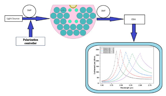
Figure 8 illustrates the schematic layout of the system incorporating the designed fiber. A broadband light source directs the incident light to a polarization controller, which ensures the light is properly polarized. The polarized light is then guided to the sensor through a single-mode fiber. The analyte is injected onto the outer surface of the sensor, and changes in the analyte’s refractive index alter the effective index of the fiber structure, causing a shift in the resonance wavelength toward longer wavelengths. An optical spectrum analyzer detects these wavelength shifts, and the results are processed and evaluated using a computer.
Figure 8. Schematic layout of the system incorporating the designed fiber.
Download figure:
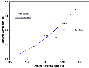
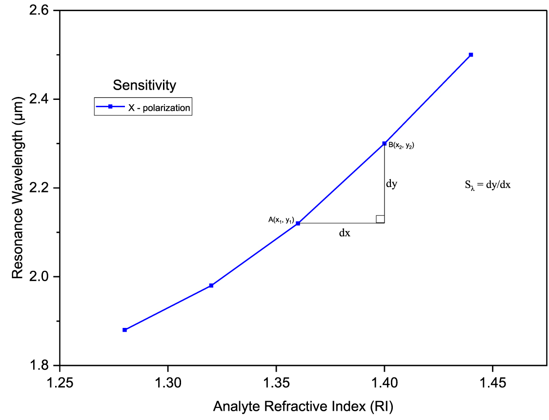
Standard image High-resolution imageIn order to consider the sensitivity of the fiber over a broad range, the average wavelength sensitivity was taken into account, which was calculated to be Sλ equal to 3875 nm RIU−1. Figure 9 displays the sensitivity profile of the proposed D-shaped PCF-based SPR sensor. As presented in table 2, the proposed design exhibits better performance regarding average wavelength sensitivity than other reported sensors.
Figure 9. Sensitivity analysis of the designed fiber-based sensor for different RI values for x-polarization.
Download figure:
Standard image High-resolution imageTable 2. Comparative study of the sensor’s performance and sensors in other recent published work.
Sensing typeDetection rangeAverage wavelength sensitivity (nm RIU−1Resolution (RIU)FOM (RIU−1)Wavelength range (nm)ReferencesD-shaped PCF-SPR sensor for humidity level detection1.33–1.341106.1——540–650[53]D-shaped PCF fiber with bi-metallic layer1.28–1.363010
Comments (0)