
Remember me
Next, in this section and below, we will report the results of a more detailed evaluation for mini-LED backlight unit. Considering the possibility of deviation between the simulation and the actual measurement, actual samples were prepared for three levels in addition to P4-3 selected in the simulation and the angle of the prism was changed, and module evaluation was performed. We have fabricated a diffuser film using our proposed structure (i.e. with the the angle-selective filter shown in Fig. 2 and prism pattern 4 shown in Fig. 5), with the configuration of the evaluated prototype module.
Mini-LED chips (manufactured by Genelites) were mounted at a pitch of 6 mm in both the x and y directions. The reflective film (manufactured by Toray) was drilled so that the LED position was opened, and the mini-LED substrate was prepared by attaching it to the mounting board. A 0.5 mm spacer was installed on this, and a diffuser film was installed on it so that the microprisms surface was on the LED side, and the QD film, BEF, and DBEF were sequentially laminated. Note that the QD film, BEF, and DBEF (the model numbers are unknown), were taken from a commercially available laptop PC.
We measured the visual unevenness and luminance distribution using an imaging spectroradiometer. The SR5000 (manufactured by Topcon Technohouse) was used as the measuring instrument to measure the luminance distribution in an area of 18 × 18 mm. The module structure at the time of evaluation is shown in Fig. 9, and the information on the components used for module evaluation is as follows:
Fig. 9
Constitution of backlight unit evaluation
The mini-LED chip features a square configuration measuring 6 mm and is manufactured by Gene Lite with the model number B0815ACQ0. The reflective film has a reflectance of 90%, as shown in spectral Fig. 9, and is 60 µ thick, supplied by Toray.
The quantum dot (QD) film has a thickness of 75 μm, but the manufacturer and model number are unknown. The BEF (Brightness Enhancement Film) has a thickness of 90 μm, with the model number BEF4-DT-90 from 3 M, though the manufacturer is not specified. Lastly, DBEF (Dual Brightness Enhancement Film) has a thickness of 117 μm, with the model number DBEF-QV2 from 3 M, but the manufacturer is also listed as unknown.
4.2 Experimental results and comparison of DOE and microprisms designsThe module evaluation results are shown in Fig. 10. Pattern B, which has high uniformity and light utilization efficiency, was selected. Pattern A has a groove angle of 147 degree and a rise angle of 16.5 degree from the angle-selective filter.
Fig. 10
Results of module evaluation1 (microprisms apex exam)
To enhance luminance uniformity and light utilization efficiency, which are often inadequate when relying solely on the angle-selective filter, we propose the incorporation of a microprisms layer. This microprisms layer is specifically designed with a rectangular arrangement of LEDs as the target configuration. The primary objective is to effectively redistribute light incidents at low angles of incidence into higher angles before it interacts with the angle-selective filter.
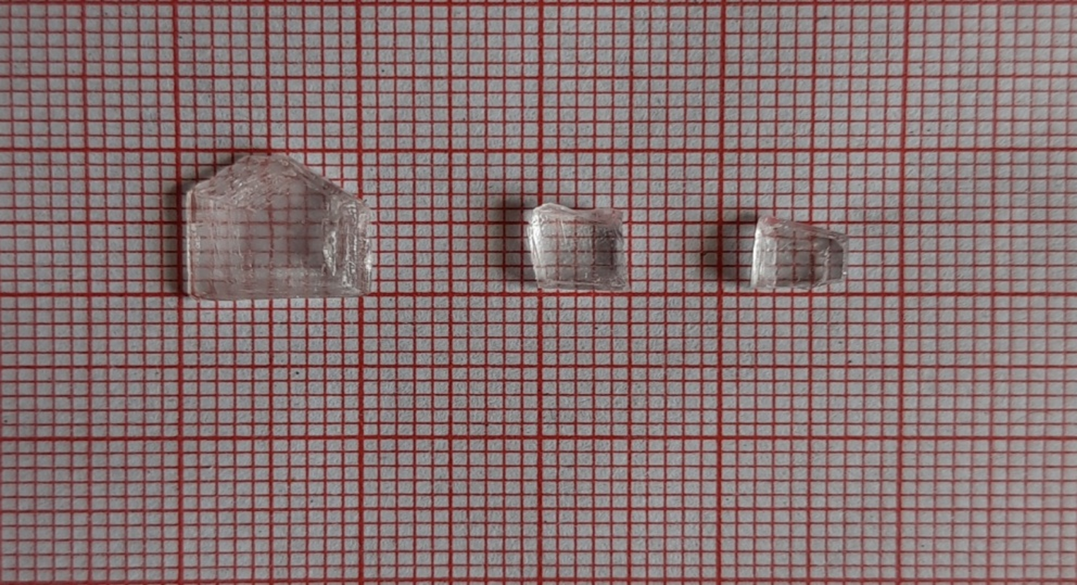
In this study, we present findings from our examination of the height of a microprisms configured with right triangular elements arranged in a three-level planar view. The prism design comprises multiple right triangular prism elements, each with a length of 100 μm. When the size of these triangular prism elements is equal to or smaller than the LED size, the light emitted from the LED’s light-emitting surface can be irradiated at all angles of the microprisms, allowing it to enter the eight distinct surfaces created by the microprisms. Under these conditions, precise alignment between the LED and the prism is unnecessary.
4.3 Interpretation of light-guiding mechanism and performanceTaking vertically emitted light from the LED as an example, this light is refracted into eight directions at the interface between the air and the microprisms, subsequently entering the angle-selective filter. The use of right-angle triangular prism elements facilitates an increase in the proportion of light refracted in specific directions, enabling the light rays to be redirected away from the LED’s top surface, allowing for effective lateral propagation. Consequently, this prism structure can divide light into eight directions, effectively transforming one LED into the functional equivalent of eight virtual LEDs.
The blue light that is divided into eight parts is reflected by the angle-selective filter and subsequently reflected by the reflective layer of the LED substrate, allowing it to spread laterally. This phenomenon significantly mitigates Mura effects on the LED. The relationship between the prism apex angle and the measured luminance distribution shows that varying apex angles yield different luminance characteristics. A larger apex angle results in a diminished splitting effect, while a smaller prism angle allows the dielectric multilayer to transmit light directly, necessitating careful selection of an angle that directs blue light laterally while reflecting the dielectric multilayer. Certain configurations demonstrate highly uniform luminance distributions. The uniformity of luminance can be quantified using an imaging luminance meter, defined as the ratio of minimum to maximum luminance measured from the light emitted by the angle-selective filter.
By integrating an optical path conversion layer optimized for the angle-selective filter, we can efficiently guide LED light from the LED substrate to the diffuser film, thereby enhancing illuminance uniformity. The deflection caused by the optical path conversion layer reduces the total number of reflections between the reflector and the diffuser film, simultaneously improving efficiency and reducing nonuniformity (Mura). Figure 11 describes the mechanism.
Fig. 11
Behavior of angle-selective filter, microprisms, diffuser film in mini-LED backlight unit
The mechanism by which Microprisms’ Pattern B operates is as follows: when utilizing an LED with a Lambertian light distribution, a significant portion of light is emitted perpendicularly to the LED surface. The angle filter serves to reflect straight light while transmitting oblique light. In contrast, the optical path conversion layer selected for this study is designed to refract light into eight directions based on their geometric configuration. By limiting the refracted angle to 30° or less—an angle that is critical for maximizing reflectance at the angle-selective filter—the light refracted in eight directions is effectively reflected by the angle-selective filter, resulting in a directional light direction oriented towards the LED substrate. However, in Pattern A, the refraction angle is insufficiently large, leading to inadequate in-plane refraction. Consequently, this results in an increased number of multiple reflections between the diffuser film and the LED substrate, diminishing the prism’s effectiveness. In contrast, Pattern B allows for adequate in-plane wave guidance while maintaining a refraction angle that remains within the reflection band of the angle-selective filter. The light generated in eight directions by the diffuser film is subsequently reflected by the LED substrate’s reflector, propagating laterally. In a virtual sense, this configuration enables one LED to function as if it were eight distinct LEDs. By facilitating horizontal propagation and ensuring that light emitted from the upper surface of the diffuser film strikes the angle-selective filter at angles of 30 degrees or greater, we achieve enhanced surface uniformity. Our findings demonstrate that the optimized combination of the angle-selective filter and optical path conversion layer maximizes the efficacy of the diffuser film.
4.4 Display effect evaluationFigure 12 compares commercially available film, an angle-selective filter only, and an angle-selective filter and optical path conversion layer. Commercial available films have function of widening light distribution, but they’re not enough to improve mura when using commercial film only.
Fig. 12
Results of module evaluation2
The addition of the layer is implemented as an actual backlight unit, and the results of the module evaluation are shown. According to the result, the DOE configuration was numerically the same as that of angle-selective filter only, and the microprisms configuration improved both uniformity and light utilization efficiency. The reason why the effect could not be obtained in the DOE configuration is that the efficiency of diffraction to 30degree was low for the blue LED, and the proportion of 0th order light that transmitted without diffraction was large, so it could not play a role as an optical path conversion layer.
To evaluate the display effect of the proposed backlight unit, we constructed a prototype module incorporating the developed diffuser film. The performance was assessed through a series of measurements focusing on luminance distribution and visual uniformity. The results demonstrated that the combination of the angle-selective filter and optical path conversion layer achieved a light utilization efficiency of 91% and a uniformity of 94%.
4.5 Comparison with conventional diffuser designsConventional diffuser designs for mini-LED backlight unit often rely on either thick scattering films (typically ~ 2 mm in thickness) or alignment-dependent masking films to achieve uniform luminance distribution. These approaches generally require a high density of LED chips and precise alignment between the LED positions and the printed masking patterns, which increases system cost and reduces manufacturing yield.
In contrast, the proposed diffuser film, composed of a dielectric multilayer angle-selective filter and an optical path conversion layer, achieves high luminance uniformity and light efficiency without any alignment requirement. Experimental results demonstrate that the proposed film can reduce the number of LED chips by 75% while maintaining high spatial uniformity with a total film thickness of only 50 μm. This level of performance is not achievable with conventional diffuser designs, especially in thin-module applications.
Additionally, because the proposed design utilizes an angle-selective filter rather than volumetric scattering, it significantly improves light utilization efficiency, which is critical for power-sensitive or high-brightness applications such as mobile devices and automotive displays.
Moreover, the advantages of our proposed diffuser technology can be extended to various lighting applications, such as architectural lighting, retail displays, and outdoor signage. By minimizing glare and maximizing light efficiency, our design can enhance the visual impact of illuminated spaces and products, creating a more engaging environment for consumers. In environments such as stadiums or concert venues, where high-intensity lighting is necessary, this technology can provide uniform illumination while reducing the discomfort associated with glare, thereby improving the overall experience for audiences and performers alike.
Furthermore, a flowchart for making these designs general-purpose designs is shown in Fig. 13. Light source conditions according to the application, Selection of optical path conversion layer (DOE or microprisms), By implementing the design parameters, it is possible to make optimization settings according to the application and purpose. As an example, Fig. 14 shows the results of a simulation with a modified OD for diffuser film using microprisms in P4-4. Changing the OD changes the optimal design. By proceeding with the study in Fig. 13, it is possible to proceed with optimization when the conditions change.
Fig. 13
Flowchart of optimization
Fig. 14
Change in optical properties when changing OD
Comments (0)